Locking structure of the connector

A technology of locking structure and connector, which is applied in the direction of connection, parts of connection device, device for preventing wrong connection, etc., can solve the problem of lock arm 109 breakage, etc., and achieve the effect of reducing size

Active Publication Date: 2016-04-06
YAZAKI CORP
View PDF7 Cites 0 Cited by
  • Summary
  • Abstract
  • Description
  • Claims
  • Application Information

AI Technical Summary

Problems solved by technology

As a result, the locking arm 109 may break

Method used


Image

  • Locking structure of the connector
  • Locking structure of the connector
  • Locking structure of the connector

Examples


Embodiment Construction

[0045] Referring to the drawings, the locking structure of the connector in the embodiment according to the present invention will be described in detail.

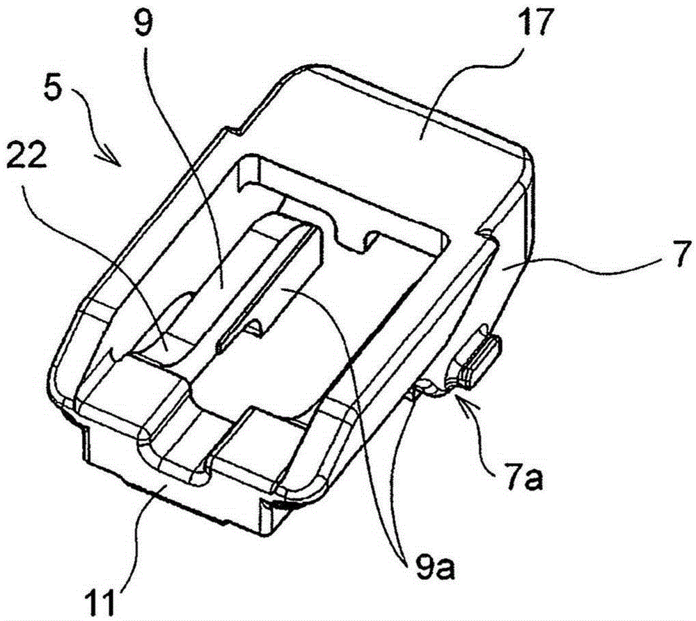
[0046] as in figure 1 As shown in , both sides of the locking portion 5 of the female connector housing (second connector housing) 1 in this embodiment are formed as half arrows extending in the fitting direction (longitudinal direction of the locking portion 5) shape, and the release lever portion 7 is formed by these sides. Front edge portion 11 extending on the entire width in the lateral direction is at the front end portion (in figure 1 Formed in the end at the front side in).

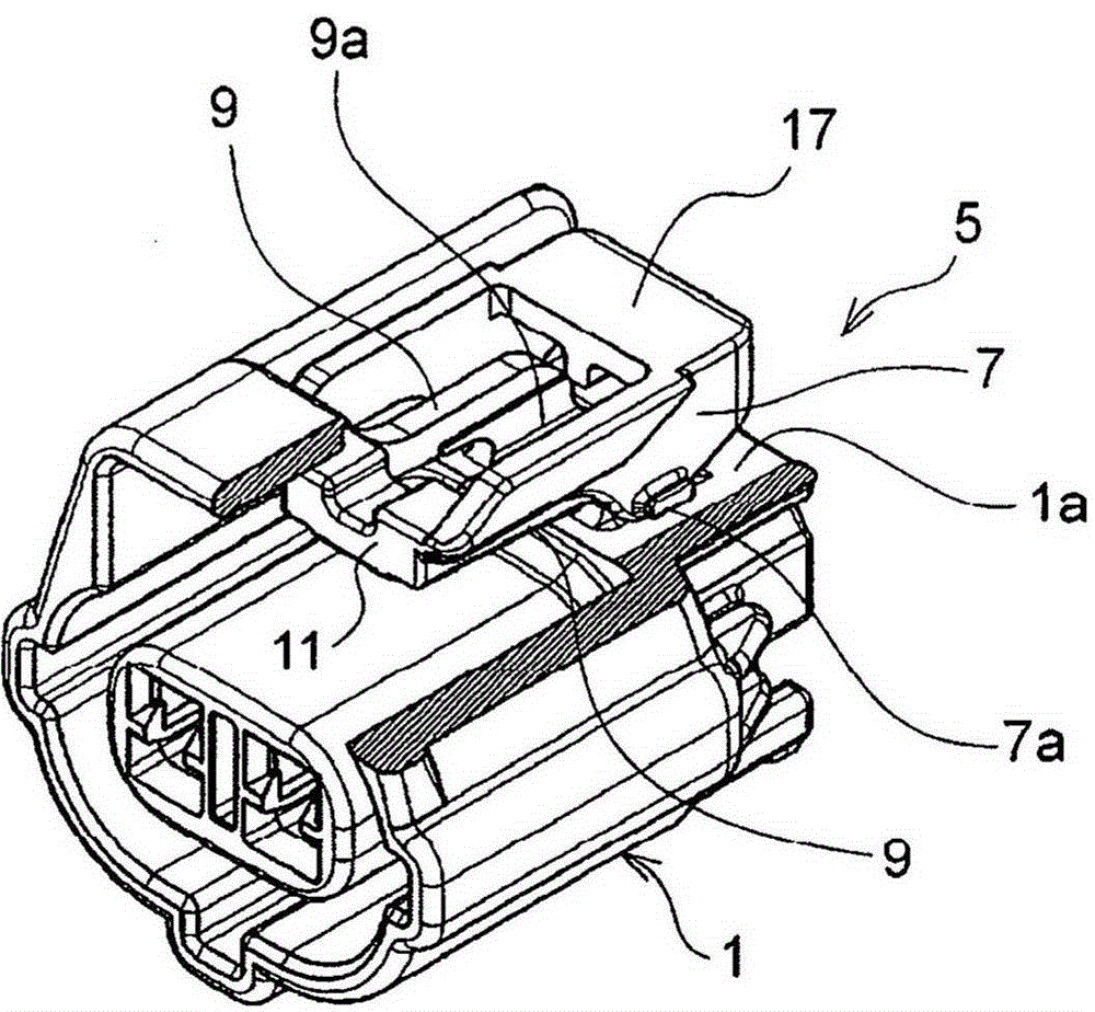
[0047] Two locking arms 9 having a plate-like shape extend substantially horizontally rearward from the front edge portion 11 . as in figure 2 As shown in , the respective rear ends of the two locking arms 9 (in figure 1 at the deep side) is bent downward, and is formed to be connected to the base end portion 9 a of the horizontal wal...


PUM


Abstract

A locking structure of a connector includes a flexible locking arm, a locking joint, and a release lever. A flexible locking arm fixed at its base end to the second connector housing extends in the fitting direction of the connector. A locking engagement portion provided at a tip portion of the flexible locking arm is configured to lock with a locking portion provided in the first connector housing. A release lever portion connected to the lock joint extends along the flexible lock arm and is configured to rotate with the lock joint about a pivot that is movable upon unlocking. The thickness of the flexible locking arm gradually decreases from the base end portion to the locking engagement portion.

Description

technical field [0001] The invention relates to a locking structure of a connector. Background technique [0002] As a conventional connector locking structure, there have been disclosed such as in Figure 5 and 6 The locking structure shown in (see PTL1). Figure 5 is an overall perspective view of the locking portion, and Figure 6 is a partial sectional view showing a locking portion in the female connector housing. [0003] Both side faces of the lock portion 105 in the female connector housing 101 are formed in the shape of a half arrow extending in the fitting direction, and a release lever portion 107 is formed by these side faces. At the front end of the release lever portion 107 ( Figure 5 In the end portion at the front side in), the front edge portion 111 is formed so as to extend over the entire width in the lateral direction. Two locking arms 109 having a plate-like shape extend substantially horizontally rearward from the front end portion 111 . as in Fi...

Claims


Application Information

Patent Timeline
Patent Type & Authority Patents(China)
IPC IPC(8): H01R13/627
CPCH01R13/6272H01R13/639H01R13/52H01R13/627H01R13/64
Inventor 滨井强久保田浩正
Owner YAZAKI CORP
Why Eureka
Try Eureka