Roller conveying line and tilter for same

A technology of turning device and conveying line, applied in the direction of conveyor objects, transportation and packaging, roller table, etc., can solve the problems of large volume, no turning objects, and heavy weight.

Active Publication Date: 2014-05-14
HANGZHOU ZHONGYA MACHINERY CO LTD
View PDF7 Cites 12 Cited by
  • Summary
  • Abstract
  • Description
  • Claims
  • Application Information

AI Technical Summary

Problems solved by technology

Since the existing roller conveyor line mainly conveys heavy

Method used


Image

  • Roller conveying line and tilter for same
  • Roller conveying line and tilter for same
  • Roller conveying line and tilter for same

Examples


Embodiment Construction

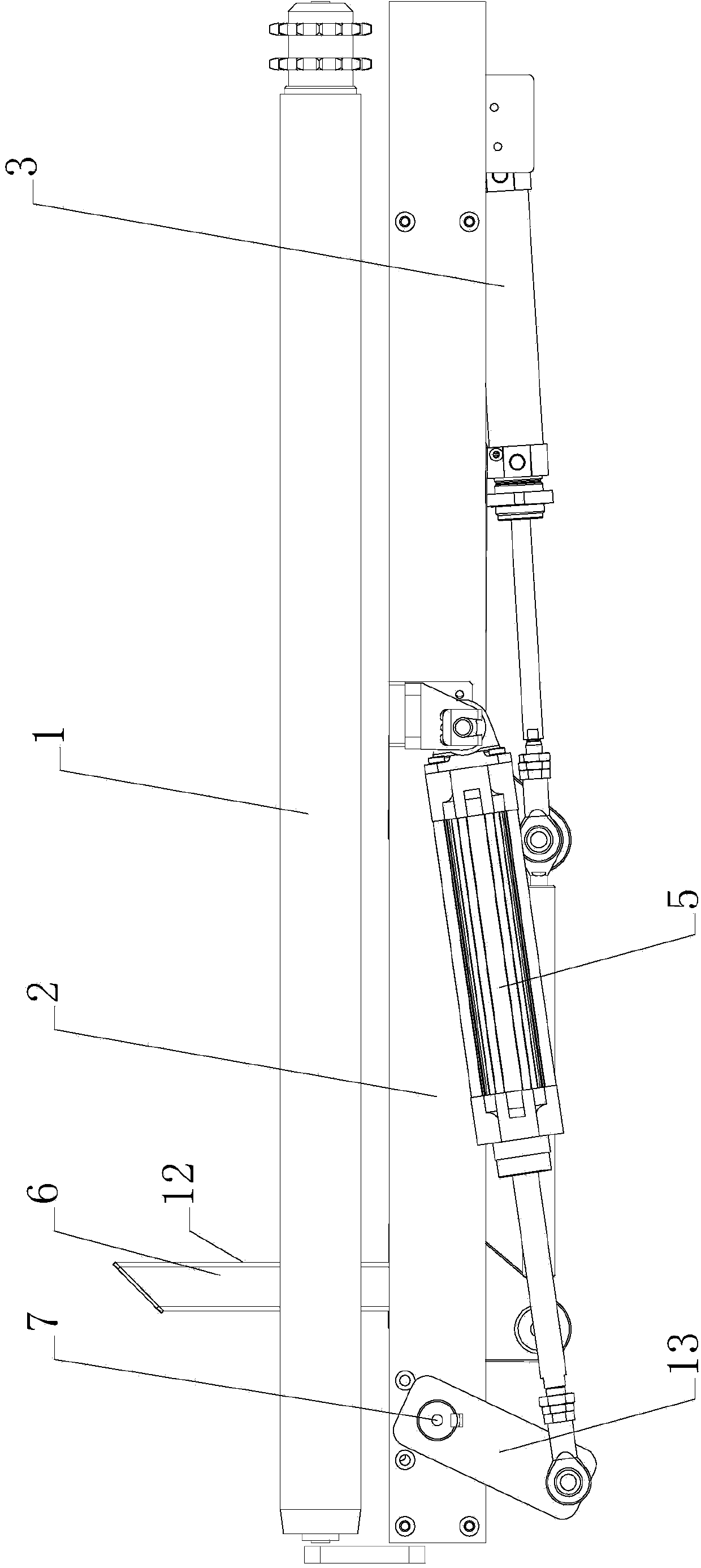
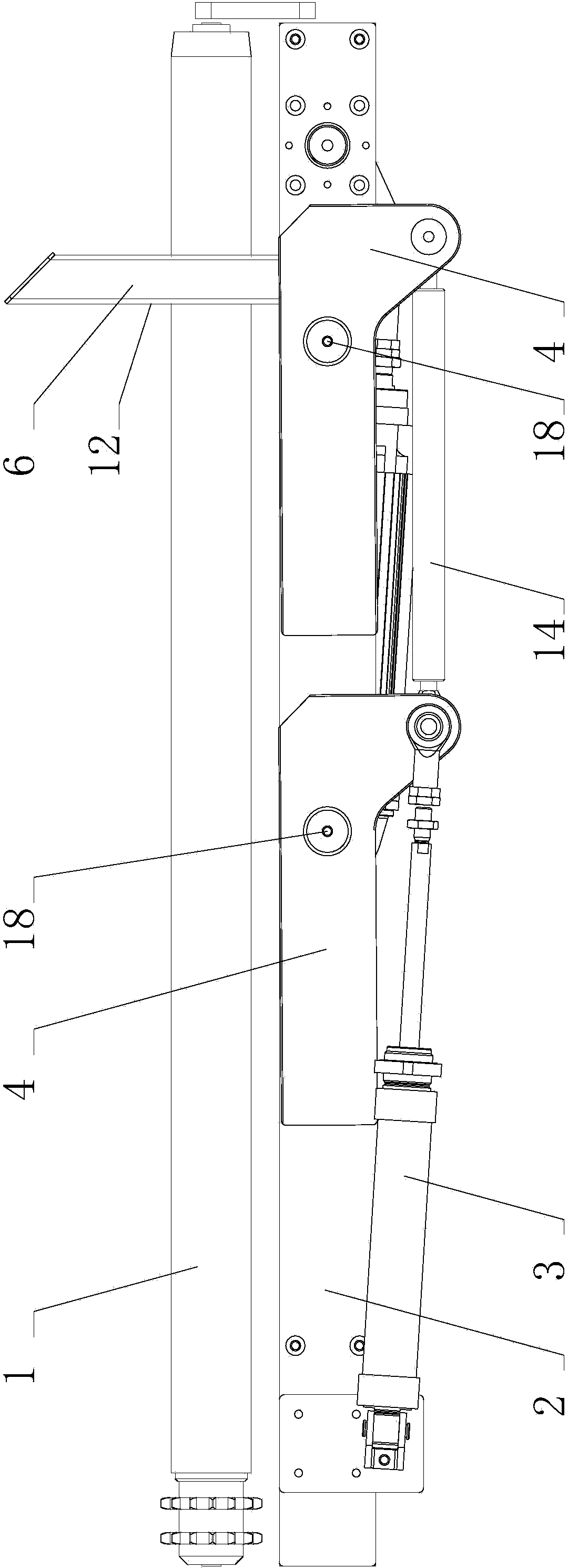
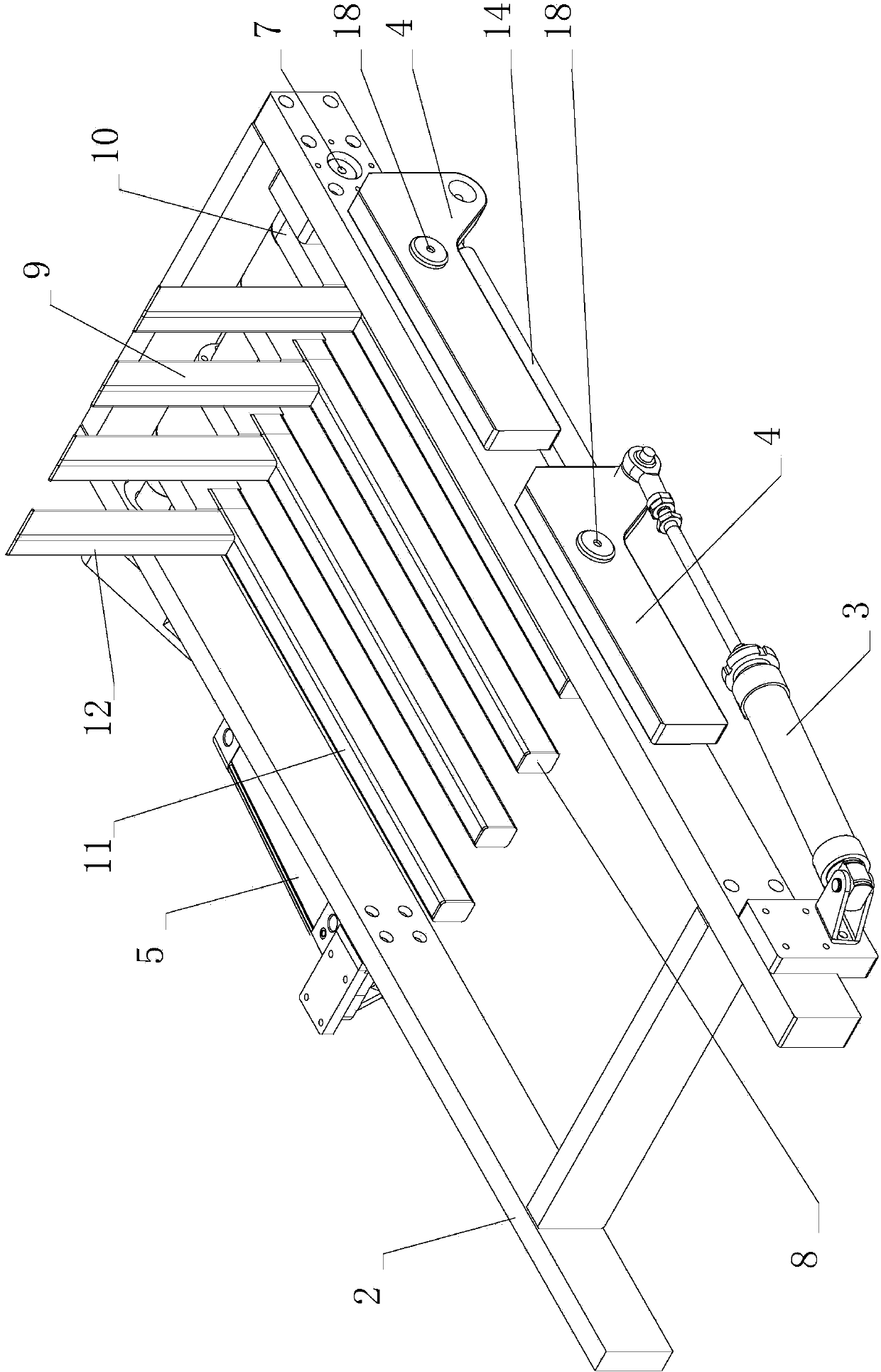
[0023] The first embodiment of the present invention, such as figure 1 , 2 , 3, 4, and 5, the roller conveyor line includes a frame, a roller 1, and a turning device. Both ends of the rollers 1 are connected to the frame, and the rollers 1 are distributed at equal intervals on the frame; the upper parts of all the rollers 1 form a working surface for transporting articles. Turning device is installed on the frame, it is positioned at the bottom of roller 1.

[0024] The overturning device includes a blocking assembly, an overturning assembly and a mounting frame 2 . The mounting frame 2 is a frame with a rectangular structure, the turning component is located inside the mounting frame 2 , and the blocking component is located outside the mounting frame 2 . The blocking assembly includes cylinder I3 and baffle plate 4. The cylinder body of the cylinder I3 is fixed on the installation frame 2, and two baffle plates 4 are installed on the installation frame 2. The baffle pla...


PUM


Abstract

The invention discloses a roller conveying line and a tilter for the same. The roller conveying line comprises rollers arranged at the same interval. The tilter is arranged below the rollers and comprises a stop component and a tilting component. The stop component and the tilting component run in a range intersecting with a working face. The stop component is used for stopping articles in a conveying direction, and by the tilting component, the stopped articles are then tilted, and particularly are separated from the conveying working face and tilted to one side thereof. The articles can be tilted within the article conveying area by the aid of the tilter arranged on the roller conveying line, in other words, the roller conveying line has an article tilting function.

Description

technical field [0001] The invention relates to a roller conveying line, especially a roller conveying line with an overturning device. Background technique [0002] The roller conveyor line is suitable for conveying all kinds of boxes, bags, pallets and other items. Bulk materials, small items or irregular items need to be transported on pallets or in turnover boxes. The roller conveyor line can convey a single piece of heavy material, or withstand a large impact load. The roller conveyor line is suitable for conveying items with a flat bottom, and is mainly composed of rollers, racks, drives and other parts. The rollers are distributed on the frame in an equidistant state, and there is an obvious gap with a large width between adjacent rollers. Since the existing roller conveying line mainly conveys heavy and bulky objects, there is no device for overturning the objects. Contents of the invention [0003] The technical problem to be solved by the present invention is ...

Claims


Application Information

Patent Timeline
IPC IPC(8): B65G47/248B65G13/00B65G13/11
Inventor 史中伟吉永林姜钰
Owner HANGZHOU ZHONGYA MACHINERY CO LTD
Why Eureka
Try Eureka