Eureka AIR delivers breakthrough ideas for toughest innovation challenges, trusted by R&D personnel around the world.

Brushless direct current motor having sfoc control

A technology of DC motors and adjustment devices, which is applied in electronic commutation motor control, electrical components, electronic commutators, etc., and can solve problems such as technical cost

Active Publication Date: 2014-05-28
SIEMENS SWITZERLAND
View PDF7 Cites 0 Cited by
  • Summary
  • Abstract
  • Description
  • Claims
  • Application Information

AI Technical Summary

Problems solved by technology

[0024] Although the behavior of EP 2 120 323 B1 leads to technically satisfactory results in regulation, it is technically expensive to implement

Method used


Image

  • Brushless direct current motor having sfoc control
  • Brushless direct current motor having sfoc control
  • Brushless direct current motor having sfoc control

Examples


Embodiment Construction

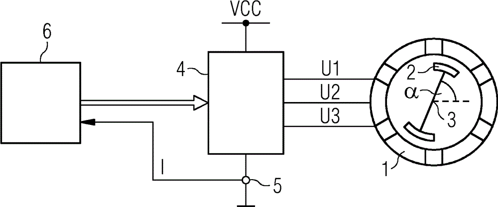
[0039] according to figure 1 , a brushless DC motor has a stator 1 and a rotor 2. The rotor 2 is mounted rotatably about an axis of rotation 3 relative to the stator 1 .

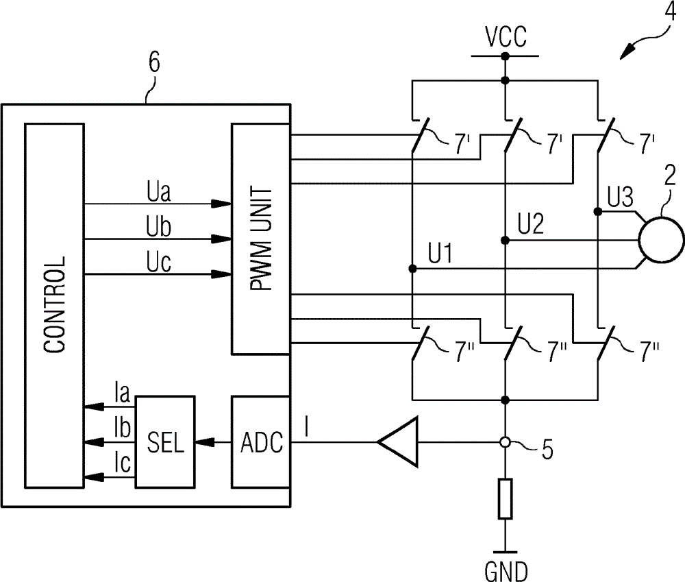
[0040] The DC motor also has an adjustment device 4 . The phases U1 , U2 , U3 of the DC motor can be switched to the supply voltage VCC by means of the regulating device 4 . A single current detection device 5 is arranged downstream of the adjustment device 4 .

[0041] The DC motor also has a control device 6 . In particular, the control device 6 can be designed as a programmable or permanently wired control device 6 . The control device 6 is connected to the adjustment device 4 so that the control device 6 can actuate the adjustment device 4 . The control device 6 is also connected to the current detection device 5 so that the control device 6 can receive the total current I respectively detected by the current detection device 5 . The control device 6 is programmed or configured in such a way that i...


PUM


Abstract

The invention relates to a control device (6) for a brushless direct current motor which determines target voltages (Ua, Ub, Uc) for phases thereof (U1, U2, U3) using a rotational position (alpha) of a rotor (2) of the direct current motor. The control device (6) accordingly controls an actuator (4) so that each phase (U1, U2, U3) is switched on to a supply voltage (VCC) within a respective timing cycle (T) during a total actuation time period (T1, T2, T3) corresponding with the respective target voltage (Ua, Ub, Uc). The control device (6) divides the timing cycles (T) into two directly successive, equally large partial cycles (T *, T") and determines a respective partial activation period (T1*, T1", T2*, T2", T3*, T3") for each phase (U1, U2, U3) for each partial cycle (T*, T").; The control device (6) determines the partial activation time periods (T1*, T1", T2*, T2", T3*, T3") so that they connect to each other, comprise the center of the respective partial cycle (T*, T"), are symmetrical thereto and together are equal to the respective total actuation period (T1, T2, T3). The control device (6) calibrates the partial actuation time periods (T1*, T1", T2*, T2", T3*, T3") to each other so that, in at least one permanently specified time interval (Z1*, Z2*) of the first partial cycle (T*), a current detection for one of the phases (U1, U2, U3) is possible and in at least one permanently specified time interval (Z1", Z2") of the second partial cycle (T"), a current detection for another of the phases (U1, U2, U3) is possible.

Description

technical field [0001] The invention relates to a control method for a brushless direct current motor, [0002] - in which the control device for a direct current motor obtains the rated voltage for the phases of the direct current motor using the rotational position of the rotor of the direct current motor, [0003] - wherein the control device actuates the regulating device as a function of the ascertained nominal voltage for the phases, so that each phase is switched on to the supply voltage during a total on-time period corresponding to the respective nominal voltage within the respective clock cycle superior, [0004] - wherein the control device divides the clock cycle into two directly successive sub-periods of the same size and ascertains for each sub-period a corresponding on-time sub-period for each phase, [0005] - wherein the control device determines for each phase a sub-on-time period such that the sub-on-time period is symmetrical to the center of the corresp...

Claims


Application Information

Patent Timeline
Patent Type & Authority Applications(China)
IPC IPC(8): H02P6/18
CPCH02P6/185
Inventor L.库塞拉C.科普夫A.胡维勒S.索特曼恩
Owner SIEMENS SWITZERLAND
Why Eureka
Eureka Blog
Learn More