A foot massager

A massager, leg and foot technology, applied in the field of health care equipment, can solve the problems of limited stimulation of the airbag to the legs, unreasonable structural setting of the roller assembly, poor massage effect, etc., to achieve good massage effect, simple and reasonable structure setting, and control convenient effect

Active Publication Date: 2015-09-16
닝버풀조이일렉트로닉테크놀로지컴퍼니리미티드
View PDF4 Cites 4 Cited by
  • Summary
  • Abstract
  • Description
  • Claims
  • Application Information

AI Technical Summary

Problems solved by technology

However, its disadvantages are: firstly, because the airbags used in air pressure massage need to be inflated during use, the massage efficiency is low, and the stimulation of the airbags to the legs is limited; secondly, due to the unreasonable structure of the roller assembly, the feet The foot reflex area cannot be fully massaged during the massage, resulting in poor massage effect

Method used


Image

  • A foot massager
  • A foot massager
  • A foot massager

Examples


Embodiment 1

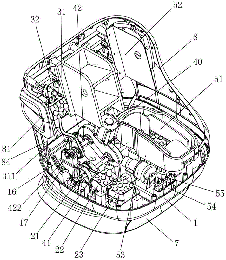
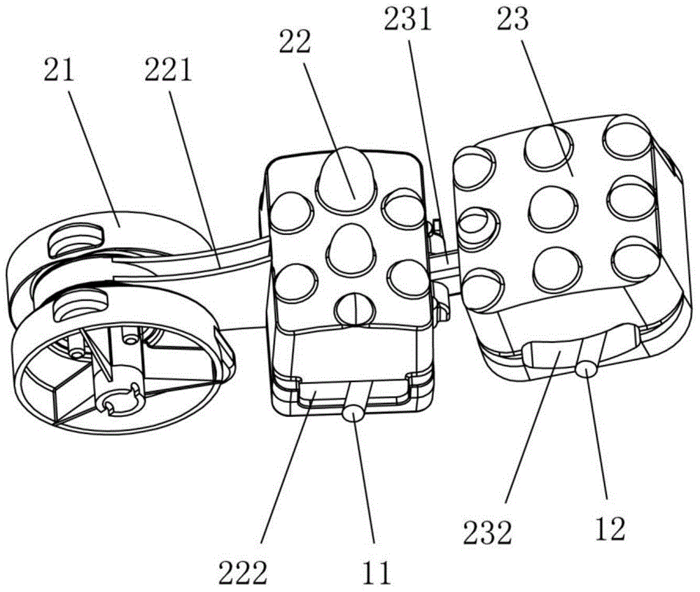
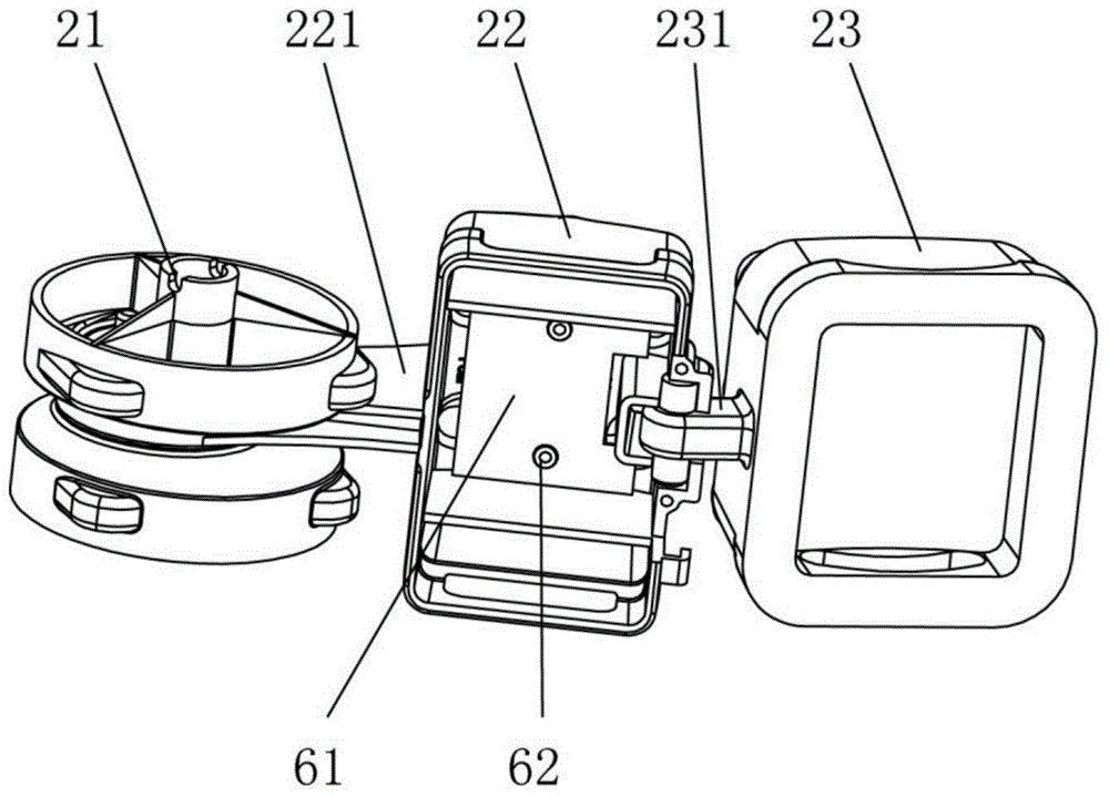
[0032] Such as Figure 1 to Figure 4 A kind of leg massager shown, comprises installation frame 1, foot massage mechanism, leg massage mechanism and driving mechanism, and described foot massage mechanism comprises heel massage roller 21, the sole massage block that is located on installation frame 1 movable 22 and the toe massage block 23, the sole massage block 22 is respectively connected with the heel massage roller 21 and the toe massage block 23, and the leg massage mechanism includes the first massage block 31 and the second massage block that are movable on the mounting frame 1 32. The first massaging block 31 is connected to the second massaging block 32. The drive mechanism includes a motor 40 fixed on the mounting frame 1, a first linkage rod 41 rotatably disposed on the mounting frame 1, and a second linkage Rod 42, the first driven wheel 411 that is fixed on the first link bar 41, and the second driven wheel 421 that is fixed on the second link bar 42, the first dri...

Embodiment 2

[0048] Such as Figure 5 Shown, as another embodiment of the present invention, a kind of leg and foot massager described in this embodiment includes mounting frame 1, foot massage mechanism, leg massage mechanism and driving mechanism, and described foot massage mechanism includes Heel massage roller 24, foot massage roller 25, and the toe massage block 23 that is movable on the mounting frame 1, the foot massage roller 25 is connected with the transmission of the toe massage block 23, and the leg massage mechanism includes a movable body that is located on the mounting frame. The first massaging block 31 and the second massaging block 32, the first massaging block 31 and the second massaging block 32 are in transmission connection, and the driving mechanism includes a motor 40 fixedly arranged on the installation frame 1, a first linkage rod 41, a second The linkage rod 42, the third linkage lever 43, the first driven wheel 411 fixed on the first linkage lever 41, the second...


PUM


Abstract

The invention discloses a leg and foot massager. The leg and foot massager comprises an installing frame, a foot massaging mechanism, a leg massaging mechanism and a drive mechanism. The foot massaging mechanism comprises a heel massaging idler wheel, a sole massaging block and a tiptoe massaging block. The sole massaging block is in transmission connection with the heel massaging idler wheel and the tiptoe massaging block. The leg massaging mechanism comprises a first massaging block and a second massaging block, wherein the first massaging block is in transmission connection with the second massaging block. The drive mechanism comprises a motor, a first linkage rod, a second linkage rod, a first driven wheel and a second driven wheel, wherein the first driven wheel is fixedly arranged on the first linkage rod, and the second driven wheel is fixedly arranged on the second linkage rod. The heel massaging idler wheel is fixedly arranged on the first linkage rod, and the second linkage rod is in transmission connection with the first massaging block. The leg and foot massager is simple and reasonable in structure, convenient to control, high in massaging efficiency, large in force of stimulation to legs and feet, good in massaging effect, and capable of completely massaging the sole reflecting zone.

Description

technical field [0001] The invention relates to a health care device, in particular to a massager for legs and feet. Background technique [0002] Leg and foot massager is a relatively common health care equipment. By massaging the legs and feet, it can relieve the tired body and relax the body and mind. Leg and foot massagers usually include a foot massage section and a leg massage section. Existing leg and foot massagers are usually equipped with a roller assembly in the foot massage section to massage the user's feet through mechanical massage; air bags are installed in the leg massage section to massage the user's legs through air pressure massage. However, its disadvantages are: firstly, because the airbags used in air pressure massage need to be inflated during use, the massage efficiency is low, and the stimulation of the airbags to the legs is limited; secondly, due to the unreasonable structure of the roller assembly, the feet The reflex area of ​​the plantar cann...

Claims


Application Information

Patent Timeline
Patent Type & Authority Patents(China)
IPC IPC(8): A61H39/04A61H15/00A61H23/04A61H7/00
Inventor 陈良飞
Owner 닝버풀조이일렉트로닉테크놀로지컴퍼니리미티드
Why Eureka
Try Eureka