Supercharge Your Innovation With Domain-Expert AI Agents!

Suspension wishbone structure for vehicle and vehicle having same

A cross arm and vehicle technology, which is applied in the direction of the cantilever, suspension, and vehicle parts installed on the pivot, can solve the problems of heavy assembly weight, poor bending resistance, stretching cracking, etc., to improve the overall performance, Effect of improving bending resistance and increasing stiffness

Active Publication Date: 2016-04-13
精诚工科汽车系统有限公司
View PDF6 Cites 0 Cited by
  • Summary
  • Abstract
  • Description
  • Claims
  • Application Information

AI Technical Summary

Problems solved by technology

[0004] However, for the first type of suspension cross-arm structure with double-layer sheet metal snap-fit ​​welding structure, its strength and rigidity are weak, and its bending resistance is poor, although this can be improved by using higher-strength steel plates or thicker plates. problem, but it will increase the quality and volume of the suspension cross-arm structure, increase the cost, and reduce the performance of the suspension cross-arm structure, and the improvement effect is general
[0005] For the second type of suspension cross-arm structure with overlapping welding of the main body and the sealing plate, the manufacturability is poor, the product drawing depth is large, the shape of the coil spring seat is strict, the material is seriously thinned, and it is easy to cause drawing cracks , needs to use a thicker plate, and at the same time needs to cooperate with the integral sealing plate, the weight of the assembly is large, the cost of processing and materials is high, and the strength and bending resistance are average

Method used


Image

  • Suspension wishbone structure for vehicle and vehicle having same
  • Suspension wishbone structure for vehicle and vehicle having same
  • Suspension wishbone structure for vehicle and vehicle having same

Examples


Embodiment Construction

[0026] Embodiments of the present invention are described in detail below, examples of which are shown in the drawings, wherein the same or similar reference numerals designate the same or similar elements or elements having the same or similar functions throughout. The embodiments described below by referring to the figures are exemplary and are intended to explain the present invention and should not be construed as limiting the present invention.

[0027] In describing the present invention, it should be understood that the terms "center", "longitudinal", "transverse", "length", "width", "thickness", "upper", "lower", "front", " Orientation or position indicated by "back", "left", "right", "vertical", "horizontal", "top", "bottom", "inner", "outer", "clockwise", "counterclockwise", etc. The relationship is based on the orientation or positional relationship shown in the drawings, and is only for the convenience of describing the present invention and simplifying the descrip...


PUM


Abstract

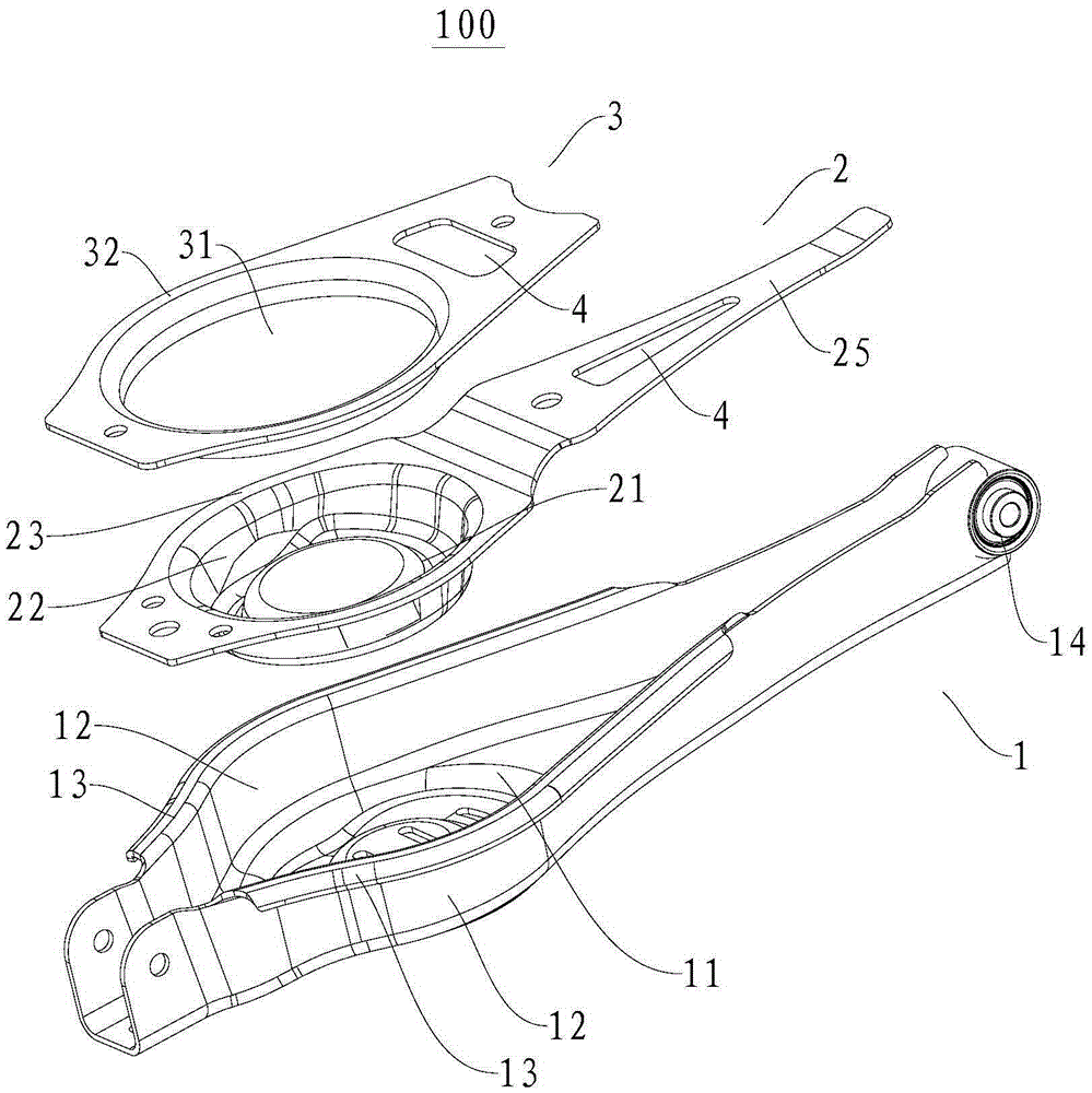
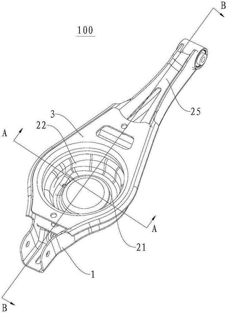
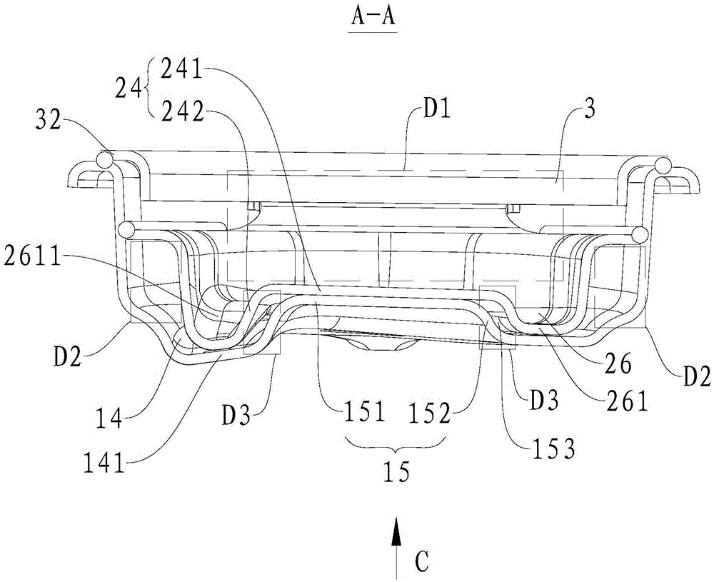
The invention discloses a suspension cross arm structure used for a vehicle and the vehicle comprising the suspension cross arm structure. The suspension cross arm structure comprises a cross arm body, a reinforcing board and a sealing board, wherein the cross arm body comprises a cross arm body bottom wall and cross arm body side walls, the cross arm body side walls are arranged on two sides of the cross arm body bottom wall and longitudinally extend along the cross arm body; the reinforcing board is arranged inside the cross arm body and fixedly welded to the cross arm body side walls and the cross arm body bottom wall, and a spring plate spiral surface is formed on the reinforcing board; the sealing board is arranged between the tops of the two cross arm body side walls, fixedly welded to the two cross arm body side walls respectively, and located above the spring plate spiral surface, and a receding through hole is formed in the sealing board. According to the suspension cross arm structure, the cross arm body, the reinforcing board and the cross arm sealing board are adopted to form the three-layer structure, a welding technology is adopted at the same time, and therefore rigidity of the suspension cross arm structure is greatly enhanced, bending resistance is enhanced, and overall performance of the suspension cross arm structure is improved.

Description

technical field [0001] The invention relates to the field of automobiles, in particular to a suspension cross arm structure for a vehicle and a vehicle with the same. Background technique [0002] The multi-link independent suspension system is widely used in automobiles, especially SUV models, due to its excellent handling stability and driving comfort, and the performance of the multi-link independent suspension system mainly depends on the suspension cross-arm structure. design. [0003] In the related technologies known to the inventor, there are mainly two types of suspension cross-arm structures of multi-link independent suspensions equipped with aluminum steering knuckles: one is a double-layer sheet metal snap-fit ​​welded structure; the other is a main body In the form of overlapping welding with the sealing plate, there can be one or two sealing plates, and when there are two sealing plates, the two sealing plates are juxtaposed at intervals along the longitudinal...

Claims


Application Information

Patent Timeline
Patent Type & Authority Patents(China)
IPC IPC(8): B60G7/00
Inventor 陆超李勇君张英富刘跃鹏刘立明
Owner 精诚工科汽车系统有限公司
Features
  • R&D
  • Intellectual Property
  • Life Sciences
  • Materials
  • Tech Scout
  • Unparalleled Data Quality
  • Higher Quality Content
  • 60% Fewer Hallucinations
Learn More