An integrated hybrid environment energy harvesting device

An energy harvesting and hybrid environment technology, applied in electromechanical devices, circuit devices, photovoltaic power generation, etc., can solve the problem of unutilized, and achieve the effect of improving high-frequency rectification and boosting circuits and broadening the working bandwidth

Active Publication Date: 2015-12-30
JIANGSU UNIV
View PDF5 Cites 0 Cited by
  • Summary
  • Abstract
  • Description
  • Claims
  • Application Information

AI Technical Summary

Problems solved by technology

[0005] Common RFID antennas are mostly in the shape of a plane ring or a plane spiral, and the central area of ​​the antenna is empty and has not been used

Method used


Image

  • An integrated hybrid environment energy harvesting device
  • An integrated hybrid environment energy harvesting device
  • An integrated hybrid environment energy harvesting device

Examples


Embodiment Construction

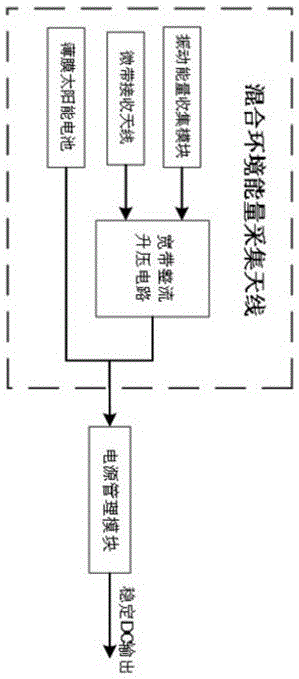
[0027] Such as figure 1As shown, the present invention is an integrated mixed environment energy harvesting device, which is composed of a thin film solar cell, a microstrip receiving antenna, a broadband rectifying and boosting circuit, and a vibration energy harvesting module. The output of the microstrip receiving antenna and the vibration energy collection module is connected to the broadband rectification and boosting circuit, the output of the broadband rectification and boosting circuit is connected to the power management module of the subsequent stage, and the output of the thin-film solar cell is directly connected to the power management module of the subsequent stage, and finally The first-level power management module outputs stable DC power.

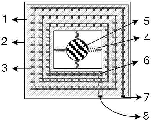
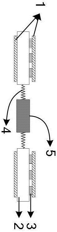
[0028] The double-layer metal printed circuit board PCB is used as the manufacturing process, and the cross-sectional view of the PCB board is as follows: Figure 4 shown. As can be seen from the cross-sectional diagram,...


PUM


Abstract

The invention discloses an integrated mixed environment energy collection device, which comprises a planar square spiral rectifying antenna, a thin-film solar cell and a permanent magnet sheet. The planar square spiral rectenna includes a microstrip receiving antenna and a broadband rectifying and boosting circuit. The thin-film solar cell is directly attached to the upper and lower surfaces of the microstrip receiving antenna. The PCB board of the microstrip receiving antenna is hollow, and the permanent magnet sheet is located in the hollow position In the middle, and connected with the double-layer PCB board in four directions through non-metallic springs. The invention can collect radio frequency electromagnetic wave energy, solar energy and mechanical vibration energy at the same time, has the characteristics of low cost, small size, portability, and wide application environment, and can be applied to wireless sensor networks, RFID and other low-power electronic devices in various environments The energy supply of the situation, in order to get rid of the shackles of the battery.

Description

Technical field [0001] The invention is an environmental energy collection field, which involves a integrated mixed environmental energy collection device. Background technique [0002] Solar, radio frequency electromagnetic wave energy and mechanical vibration energy are three common environmental energy resources.The typical power of solar cells under sunlight is MW level.When the solar light is direct, the typical thin film solar cell receives the energy of 50-100MW / CM 2 EssenceIn cloudy days or indoors, the received power will be reduced to the μW level.The film solar cells such as hydrogenation of amorphous silicon, a typical conversion efficiency of optical energy 10-20%.The thin film solar cell should reduce the conversion efficiency while reducing materials and manufacturing costs. This is currently the main challenge of the third -generation solar cell development.In addition to studying and developing low -cost and efficient solar cells, we must also strive to improve t...

Claims


Application Information

Patent Timeline
Patent Type & Authority Patents(China)
IPC IPC(8): H02S10/00H02K35/02H02J17/00H02J50/20H02J50/27
CPCY02E10/50
Inventor 徐雷钧王昌硕白雪赵不贿
Owner JIANGSU UNIV
Why Eureka
Try Eureka