Network type protection method based on closed-loop mode operation of power network

A technology of power network and closed-loop mode, applied in emergency protection circuit devices, electrical components, information technology support systems, etc., can solve problems such as slow response time and long processing time, achieve small line impact, quickly locate faults and isolate faults , fast effect

Active Publication Date: 2014-06-18
BEIJING CREATIVE DISTRIBUTION AUTOMATION
View PDF4 Cites 17 Cited by
  • Summary
  • Abstract
  • Description
  • Claims
  • Application Information

AI Technical Summary

Problems solved by technology

Each feeding terminal needs to send information to all feeding terminals, and each feeding terminal needs to es

Method used


Image

  • Network type protection method based on closed-loop mode operation of power network
  • Network type protection method based on closed-loop mode operation of power network

Examples


Example Embodiment

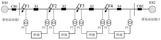
[0082] Embodiment 1, when the communication is normal, a fault occurs between the circuit breaker of the terminal unit adjacent to the substation and the substation, that is, the fault point is point F1, and the protection action process is as follows:

[0083] A. After the outgoing circuit breaker CB1 in the substation ES1 detects the fault current, it starts the quick-break protection function or the over-current protection function;

[0084] B. The intelligent controller in the terminal unit adjacent to the substation ES1 activates the quick-break protection function or the overcurrent protection function, and the circuit breaker S1 trips. thereby isolating the point of failure.

Example Embodiment

[0085] Example 2, when the communication is normal, a fault occurs between the circuit breakers of the terminal units, that is, figure 1 In the fault point F2, the protection action process is as follows:

[0086]A. The intelligent controller in the terminal unit located on one side of the fault point starts the quick-break protection function or the over-current protection function, and the circuit breaker S1 trips;

[0087] B. The intelligent controller in the terminal unit located on the other side of the fault point activates the quick-break protection function or the over-current protection function, and the circuit breaker S2 trips. thereby isolating the point of failure.

Example Embodiment

[0088] Example 3, when the communication is normal, a fault occurs between the circuit breakers of the terminal unit, that is, figure 1 In the fault point F3, the protection action process is as follows:

[0089] A. The intelligent controller in the terminal unit located on the side of the fault point starts the quick-break protection function or the over-current protection function, and the circuit breaker S2 trips;

[0090] B. The intelligent controller in the terminal unit located on the other side of the fault point activates the quick-break protection function or the overcurrent protection function, and the circuit breaker S3 trips. thereby isolating the point of failure.


PUM


Abstract

A network type protection method based on closed-loop mode operation of a power network is used for a power network system which operates in a closed-loop mode. The power network system comprises multiple transformer stations and terminal units connected to the transformer stations, and is characterized in that each terminal unit comprises an intelligent controller, a breaker and a communication module, the communication module in each terminal unit is only communicated with the closest terminal unit, and the intelligent controller in each terminal unit collects the information of voltage, current, power direction, associative direction and state and the after-fault information of the breakers in the terminal unit and the adjacent terminal unit. According to the method, a peer-to-peer communication network is adopted, the terminal units on a circuit are communicated with one another, fault information of adjacent switches is collected, arbitrating is performed, and rapid positioning and isolating of a fault are realized.

Description

technical field [0001] The invention relates to a protection method for an intelligent power network, in particular to a network-type protection method suitable for the operation of a multi-power supply ring network structure and a full circuit breaker network. Background technique [0002] Power automation is an important part of the smart power network, and it is of great significance to improve the reliability of power supply, expand the power supply capacity and realize the efficient and economical operation of the power network. Power network fault handling is the core content of power automation. my country's distribution network generally adopts radial structure lines. When carrying out urban network transformation, it generally adopts the interconnection of the ends of the radiation lines to form a hand-in-hand dual power supply ring network structure. The method saves investment and can improve the reliability of power supply. At present, the network with this struct...

Claims


Application Information

Patent Timeline
IPC IPC(8): H02H7/26G01R31/08
CPCY04S10/52
Inventor 袁钦成李春光袁启洪王娟娟董良董旭柱黄小耘于力彭飞进黄红远
Owner BEIJING CREATIVE DISTRIBUTION AUTOMATION
Why Eureka
Try Eureka