Stackable voltage generator

A voltage generator and stacking technology, applied in the direction of conversion equipment without intermediate conversion to AC, can solve the problems of unfavorable large-scale integrated circuit applications, increase of circuit cost and circuit volume, and obvious output fluctuations, etc., to reduce circuit Effects of cost, output smoothing, and quantity reduction

Active Publication Date: 2014-06-18
中山芯达电子科技有限公司
View PDF8 Cites 3 Cited by
  • Summary
  • Abstract
  • Description
  • Claims
  • Application Information

AI Technical Summary

Problems solved by technology

When it is necessary to obtain a high-voltage output, a sufficient number or capacity of capacitors must be used, which will undoubtedly increase the circuit cost and circuit volume, and do not use the application of large-scale integrated circuits
At the same time, because the pump structure charges and discharges the capacitor step by step, its response time is also long, the output fluctuation is obvious, and the efficiency is low. It is not suitable for integrated circuits that require response speed and accuracy.

Method used


Image

  • Stackable voltage generator
  • Stackable voltage generator
  • Stackable voltage generator

Examples


no. 1 example

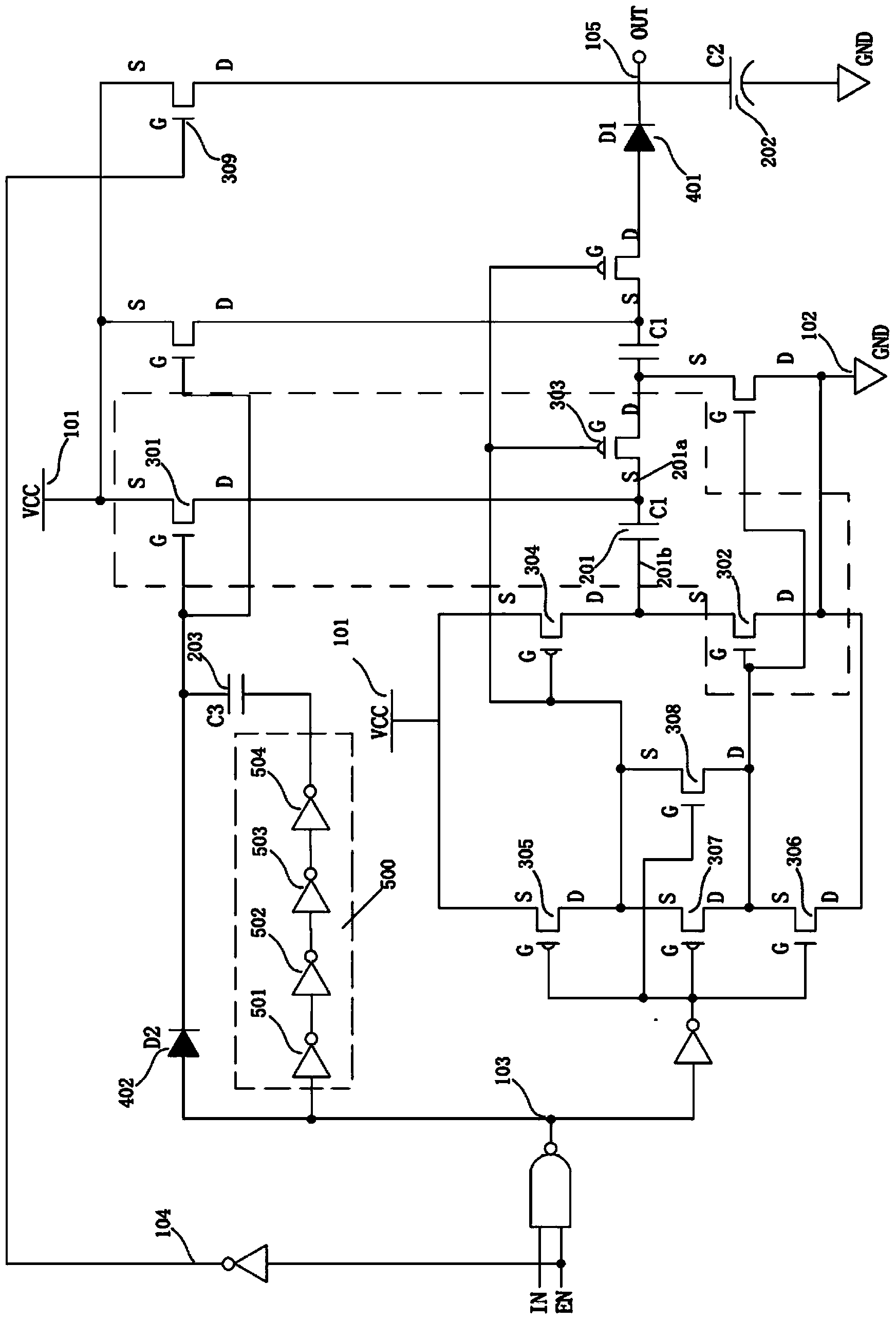
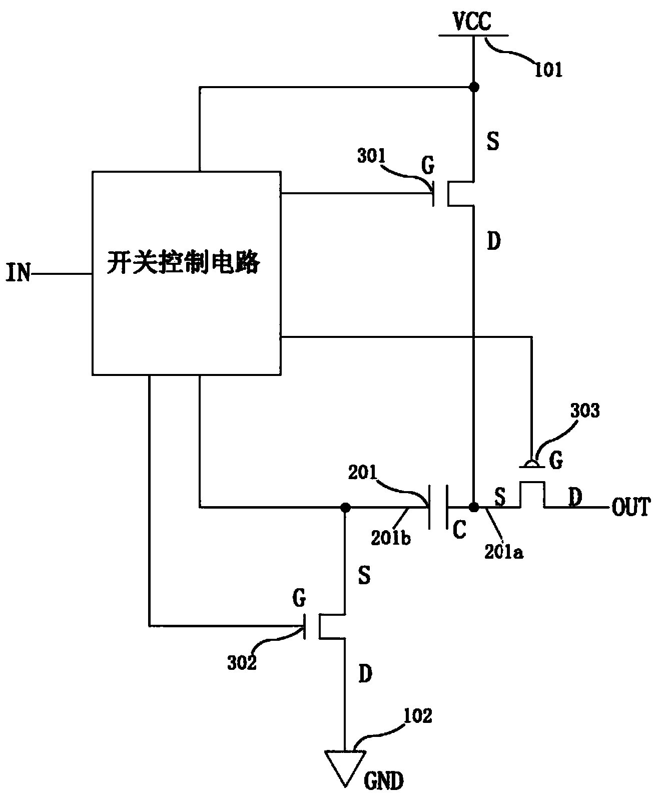
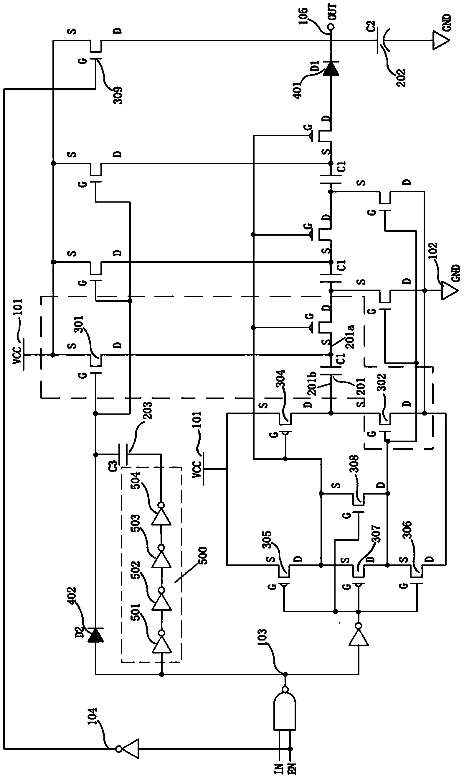
[0054] A stacked voltage generator, including a first input terminal 101, which inputs a first level signal; a second input terminal 102, which inputs a second level signal; a generator output terminal 105; at least one boost module; and switch control circuit;

[0055] The boost module is provided with an input terminal and an output terminal, which includes:

[0056] The first capacitor 201 has a first end 201a and a second end 201b, the second end 201a is connected to the input end of the module;

[0057] The first transistor 301 is connected between the first input terminal 101 and the first terminal 201a of the first capacitor 201;

[0058] The second transistor 302 is connected between the second input terminal 102 and the second terminal 201b of the first capacitor 201;

[0059] The third transistor 303, which is connected between the output terminal of the module and the first terminal 201a of the first capacitor 201;

[0060] The boost modules are sequentially conn...


PUM


Abstract

The invention provides a stackable voltage generator which is characterized by comprises a first input end, a second input end, a generator output end, at least one boost module and a switch control circuit, wherein each boost module comprises a first capacitor, a first transistor, a second transistor and a third transistor; the first capacitor is provided with a first end and a second end; the second end is connected with the input end of the module; the first transistor is connected between the first input end and the first end of the first capacitor; the second transistor is connected between the second input end and the second end of the first capacitor; the third transistor is connected between the output end of the module and the first end of the first capacitor; the boost modules are connected in series; a fourth transistor is connected between the input end of the first end boost module and the first input end; the switch control circuit is connected with the control ends of the first transistor, the second transistor, the third transistor and the fourth transistor to control the breakover or cutoff of the transistors. A boost scheme with flexible circuit structure, small size, low cost, wide application, stable voltage and rapid response is provided.

Description

technical field [0001] The invention relates to a stacked voltage generator. Background technique [0002] Generally, integrated circuits are equipped with voltage generators, whose function is to provide stable voltages of different levels for other circuit units in the integrated circuit, so as to meet the needs of power supply and source signals of each circuit unit. The voltage generator is more commonly used in a pump structure. The scheme is to superimpose the voltages of multiple parallel capacitors and series diodes step by step, as shown in Figure 5 shown. In the above pump structure, the voltage output value depends on the number of capacitors, and the current output value depends on the capacity of each capacitor. When it is necessary to obtain a high-voltage output, it is necessary to use a sufficient number or capacity of capacitors, which will undoubtedly increase the circuit cost and circuit size, and does not utilize the application of large-scale integrate...

Claims


Application Information

Patent Timeline
Patent Type & Authority Applications(China)
IPC IPC(8): H02M3/07
Inventor 方镜清
Owner 中山芯达电子科技有限公司
Why Eureka
Try Eureka