Double head anti-vibration electromagnet device
An electromagnet and anti-vibration technology, applied in the field of electromagnet devices, can solve the problem of inability to play the role of anti-theft, and achieve the effect of increasing safety performance
- Summary
- Abstract
- Description
- Claims
- Application Information
AI Technical Summary
Problems solved by technology
Method used
Image
Examples
Embodiment 1
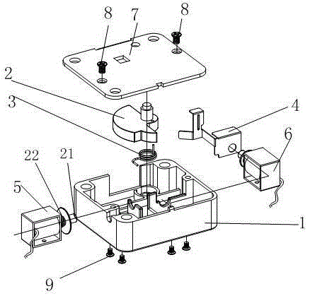
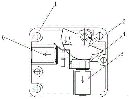
[0017] Such as figure 1 and figure 2 As shown, the double-head anti-vibration electromagnet device of the present invention includes an electromagnet base 1, a semicircle limit block 2, a limit block return spring 3, a push piece 4, a first electromagnet 5, a second electromagnet 6, and a cover plate 7 , cover plate fixing screw 8, electromagnet fixing screw 9, the first electromagnet 5 and the second electromagnet 6 are fixed on the electromagnet base 1 through the electromagnet fixing screw 9, and the semicircle limit block 2 is installed on the electromagnet base 1 , the cover plate 7 and the top of the electromagnet base 1 are fixed by cover plate fixing screws 8, and a limit block return spring 3 is provided between the electromagnet base 1 and the semicircle limit block 2, the first electromagnet 5, the second The electromagnets 6 are all connected with the push piece 4 , and the stressed part of the push piece is exposed outside the cover plate 7 , and the first elect...
Embodiment 2
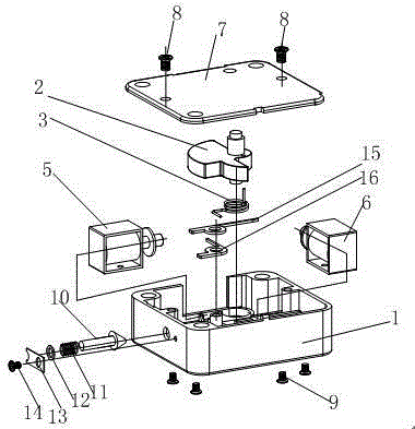
[0019] Such as image 3 and Figure 4 As shown, the second embodiment is basically the same as the first embodiment, the difference is that the first paddle 15 and the second paddle 16 replace the push piece 4 . One side of the first electromagnet 5 is connected with a push rod pin 10 , a push rod pin return spring 11 , a gasket 12 , a blocking piece 13 , and a blocking piece fixing screw 14 in sequence.
Embodiment 3
[0021] Such as Figure 5 and Figure 6 As shown, the third embodiment is basically the same as the first embodiment, the push plate return spring 17, the limit screw 18, and the push plate 19 replace the push piece 4.
[0022] In the case of no power supply, the pins on the two electromagnets are in the pop-up state under the action of the back-moving spring, and the two pins cooperate with the semicircle limit block to prevent the semicircle limit block from being forced to retreat and rotate. The first opening method: two electromagnets are energized, the electromagnets generate suction, the pins of the electromagnets shrink and retreat, and are disengaged from the matching part on the semicircle limit block, the semicircle limit block can be rotated and retreated, and the safe slide plate can move toward Move back so that the safe can be opened. The second opening method: use external force (the paddle on the emergency lock) to push the push piece on the electromagnet, an...
PUM
 Abstract
Description
Claims
Application Information
 - R&D
- Intellectual Property
- Life Sciences
- Materials
- Tech Scout
- Unparalleled Data Quality
- Higher Quality Content
- 60% Fewer Hallucinations
Browse by: Latest US Patents, China's latest patents, Technical Efficacy Thesaurus, Application Domain, Technology Topic, Popular Technical Reports.
© 2025 PatSnap. All rights reserved.Legal|Privacy policy|Modern Slavery Act Transparency Statement|Sitemap|About US| Contact US: help@patsnap.com


