
Method and device for removing a screen from a cable

A shielding and cable technology, which is applied in the field of devices for realizing this method, can solve the problems of complexity, complex removal of braided shielding, inflexibility of devices and methods, etc.

Active Publication Date: 2014-06-25
SCHLEUNIGER HLDG AG A CO INC UNDER THE LAWS OF SWITZERLAND
View PDF9 Cites 17 Cited by
  • Summary
  • Abstract
  • Description
  • Claims
  • Application Information

AI Technical Summary

Problems solved by technology

Therefore, in the case of cables, especially cables with non-circular cross-sections, cleanly removing the braided shield without damaging the various cable layers underlying the braided shield is still very complicated and currently Usually implemented manually, since the techniques mentioned above are not particularly suitable for non-circular cables and the disadvantages mentioned above occur
Most known devices are very complex and require many cable specification elements, making these devices and methods inflexible

Method used


Image

  • Method and device for removing a screen from a cable
  • Method and device for removing a screen from a cable
  • Method and device for removing a screen from a cable

Examples


Embodiment Construction

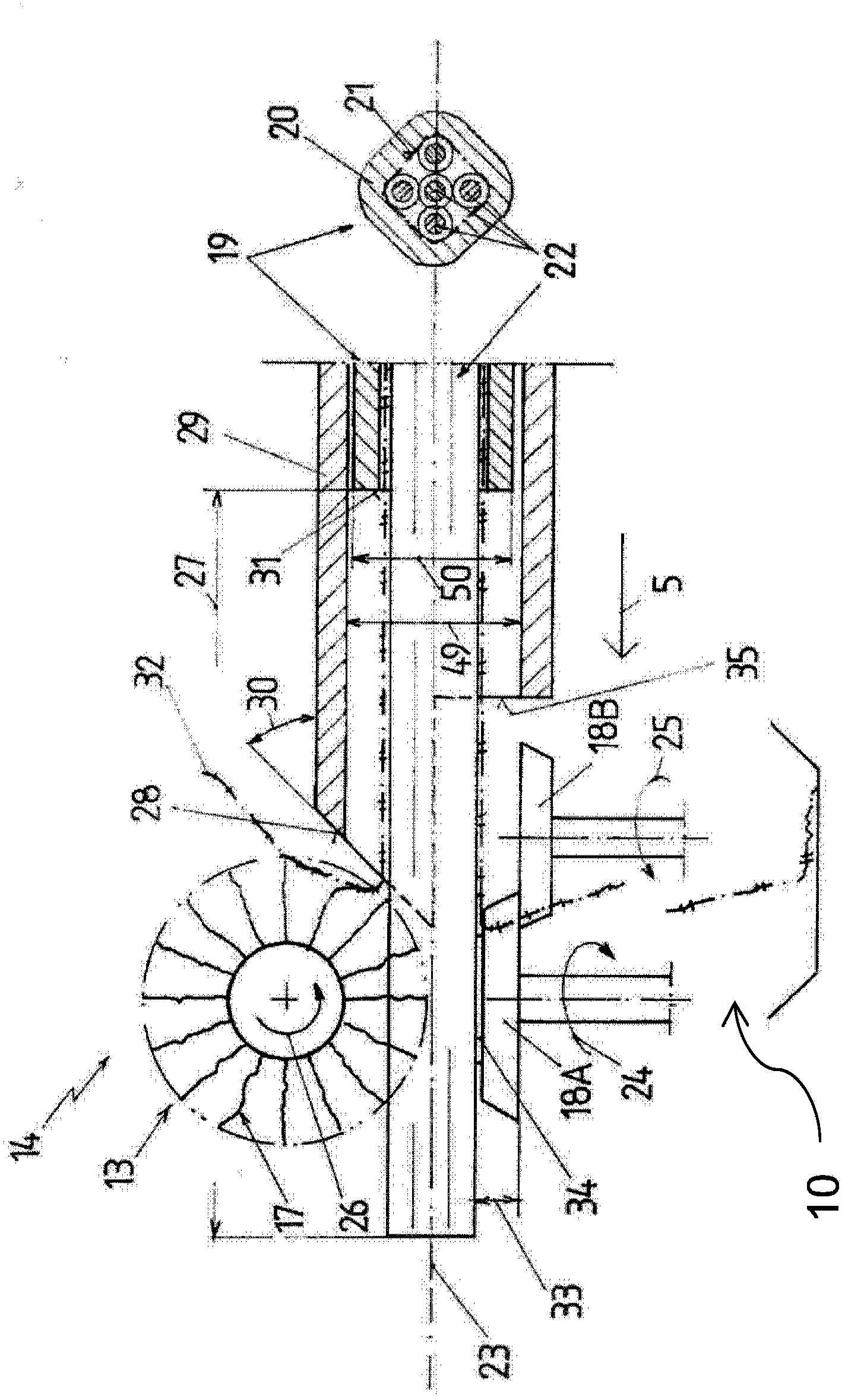
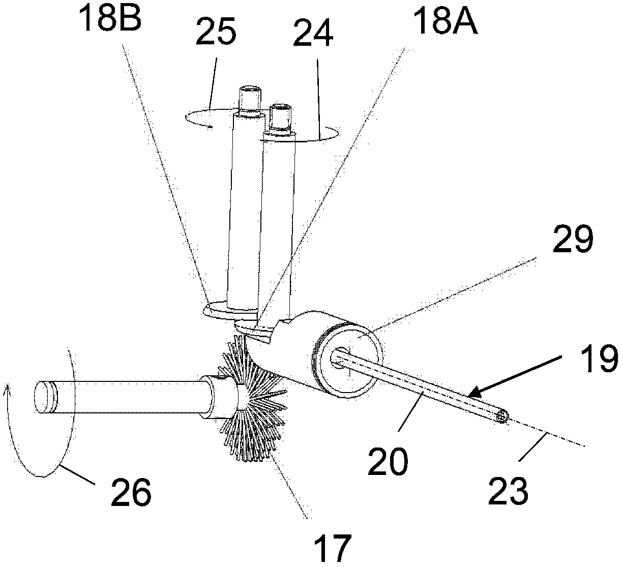
[0028] exist figure 1 is shown in schematic cross-section in the processing cable 19 ( figure 1 The right side in ) shows the basic elements of the device according to the invention in the state during cross-section). In the case shown, the cable 19 is a multiconductor cable comprising an outer sheath such as an outer insulation 20 , a preferably braided shield 21 , and five separate insulated inner conductors 22 , for example. figure 1 The cross-section of the cable 19 is shown to be clearly non-circular. It is to be understood that the cable 19 may be of any desired or required cross section and may include a specific or dedicated number and type of inner conductors 22 .

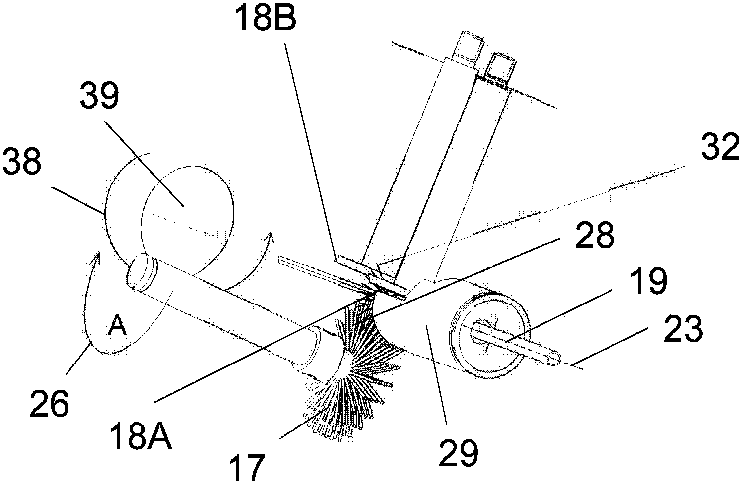
[0029] The outer sheath or insulation 20 is removed from the conductor 22 and shield 21 in the usual manner (not shown in detail herein) to expose the shield 21 in a predetermined section 27 of the cable for further processing. exist figure 1 In the depicted embodiment, a single rotating brush 17 using...


PUM


Abstract

A method is disclosed for removing a screen from a cable, which screen surrounds at least one electrical or optical inner conductor (22) and which consists in particular of a braided screen (21) from a cable (19) consisting at least of the at least one conductor (22), the screen (21) and an outer insulation (20). After baring the screen (21) at least at one end or in one section of the cable by removing the outer insulation (20), a section of the screen (21) is deformed and / or unbraided, and then the deformed section of the screen (21) is cut off at least in part. The step of deforming and / or unbraiding is accomplished by lifting off the screen (21) from the at least one inner conductor (22) on at least one end of the section of the screen (21) to be removed, at least over a part of the circumference of the cable. This step is additionally comprising or being followed by pressing the parts of the screen (21), which have been lifted off onto an erection surface (28) before cutting them off, whereby preferably the parts of the screen (21) which have been lifted off are bent backwards in the direction of the yet un-deformed screen (21).

Description

technical field [0001] The invention relates to a method for removing a shield from a cable according to the preamble of claim 1 and a device for carrying out this method according to the preamble of claim 8 . Background technique [0002] As is known, electrical or optical cables are provided with a plurality of wires with insulated conductors and at least one film surrounding at least part of the wires. The function of the membrane is an isolating and / or shielding membrane. During use in the field such cables are manually stripped to expose the individual conductors for further processing steps. The continuous surrounding film makes the insulation stripping process rather complicated. In addition, insulation stripping is required in the case of data cables comprising pairs of conductors surrounded by a film and / or if at least one side of the film is coated with an adhesive to ensure better adhesion to the conductors or to adhere the conductors to each other. The process...

Claims


Application Information

Patent Timeline
IPC IPC(8): H02G1/12
CPCH02G1/1273H02G1/1297B26D7/08H02G1/12Y10T83/343Y10T83/0419
Inventor 迈克尔·乔斯特彼特·斯特潘
Owner SCHLEUNIGER HLDG AG A CO INC UNDER THE LAWS OF SWITZERLAND
Learn More