High-voltage frequency converter and reactive compensation integrated topological structure and method

A technology of high-voltage frequency converter and topological structure, which is applied in the directions of reactive power compensation, reactive power adjustment/elimination/compensation, AC power input conversion to AC power output, etc. It can solve problems such as motor failure and IGBT damage, and prevent Inrush current, low withstand voltage, and protection from damage

Pending Publication Date: 2017-12-01
WOLONG ELECTRIC GRP CO LTD +1
View PDF4 Cites 1 Cited by
  • Summary
  • Abstract
  • Description
  • Claims
  • Application Information

AI Technical Summary

Problems solved by technology

[0003] The Chinese patent with the publication number CN 102946137 A discloses a harmonic reactive power compensation control method based on the high-voltage inverter bypass, and provides a circuit topology. The high-voltage inverter and the bypass form a parallel circuit, and the power side The circuit breaker QF1 on the motor side and the circuit breaker QF2 on the motor side are both set inside the parallel circuit, and its working principle makes the high-voltage inverter among them reversely powered by the power supply on the motor side when performing reactive power compensation, and the inverter circuit in the inverter When reverse power is supplied to the frequency converter and reactive power compensation is performed, the motor cannot be separated from the compensation circuit. This reverse power supply topology is not suitable for multi-level cascaded high-voltage frequency converters, and it is easy to cause damage to the IGBT in it, and this This topology also cannot disengage the motor in the circuit

Method used


Image

  • High-voltage frequency converter and reactive compensation integrated topological structure and method
  • High-voltage frequency converter and reactive compensation integrated topological structure and method
  • High-voltage frequency converter and reactive compensation integrated topological structure and method

Examples


Embodiment Construction

[0026] The specific embodiments provided by the present invention will be described in detail below in conjunction with the accompanying drawings.

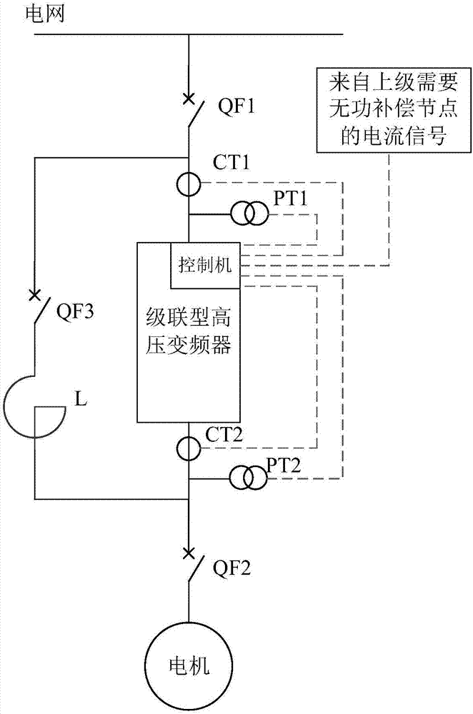
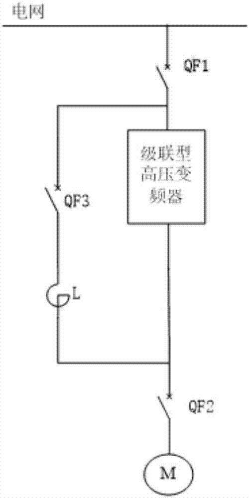
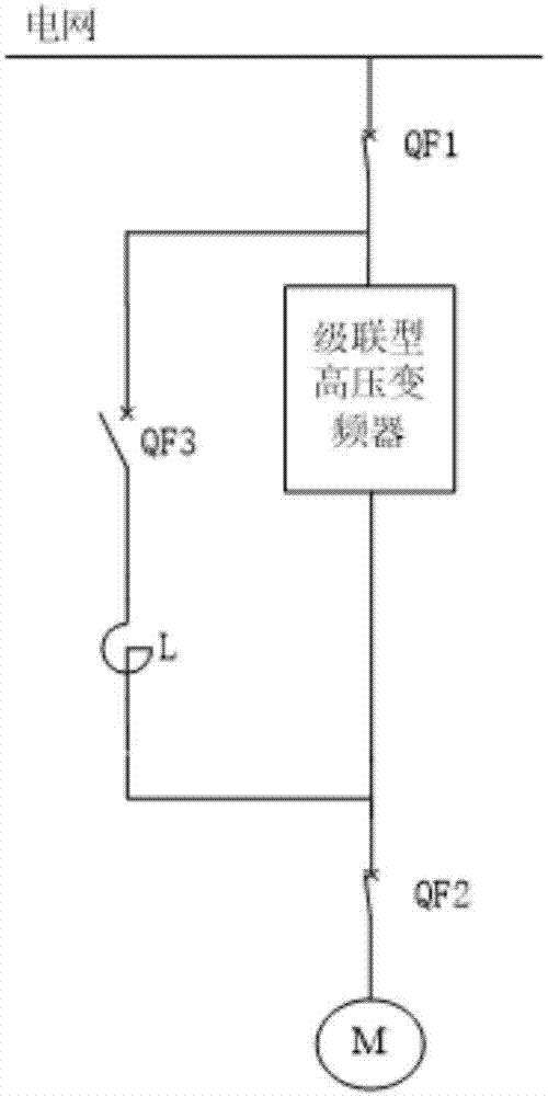
[0027] like figure 1 As shown, a high-voltage inverter and reactive power compensation integrated topology, including high-voltage inverter, power circuit breaker QF1, motor circuit breaker QF2, reactive power compensation circuit breaker QF3, reactor L, input side current sensor CT1, input side voltage sensor PT1, output side current sensor CT2, output side voltage sensor PT2.

[0028] The high-voltage frequency converter is a multi-level cascaded high-voltage frequency converter, and the reactive power compensation circuit breaker QF3 is connected in series with the reactor L to form a reactive power compensation output circuit, which is connected in parallel to the input of the high-voltage frequency converter Terminal and output end, form a parallel circuit with the high-voltage frequency converter, the power circuit breaker ...


PUM


Abstract

The invention provides a high-voltage frequency converter and reactive compensation integrated topological structure and method. The high-voltage frequency converter and reactive compensation integrated topological structure comprises a high-voltage frequency converter, a power circuit breaker QF1, a motor circuit breaker QF2, a reactive compensation circuit breaker QF3, an electric reactor L, an input side current sensor CT1, an input side voltage sensor PT1, an output side current sensor CT2 and an output side voltage sensor PT2. When the high-voltage frequency converter is used for reactive compensation, the security of internal components of the high-voltage frequency converter is protected by adopting the mode of directly providing an input end of the frequency converter with electricity through a power grid; and a motor can be freely separated and the motor and a reactive compensation device do not affect each other during reactive compensation. The multilevel cascaded high-voltage frequency converter is capable of driving the motor when the motor needs to be driven, and carrying out reactive compensation on the power grid when the motor does not need to be driven, and the security and reliability of two function applications are ensured at the same time.

Description

technical field [0001] The invention relates to the technical field of high-voltage frequency converters, in particular to an integrated topology structure and method of high-voltage frequency converters and reactive power compensation. Background technique [0002] With the algorithm technology of multi-level cascaded high-voltage inverters becoming more and more mature, the majority of frequency conversion manufacturers are expanding the functionality of frequency conversion in order to expand the frequency conversion business. Because the continuity of many multi-level cascaded high-voltage inverters driving motors is not high, the motors are often in standby or maintenance status, which is a great waste for high-priced multi-level cascaded high-voltage inverters. Since the multi-level cascaded high-voltage inverter itself and some auxiliary equipment can realize the bidirectional reactive power compensation function, if the multi-level cascaded high-voltage inverter can ...

Claims


Application Information

Patent Timeline
Patent Type & Authority Applications(China)
IPC IPC(8): H02J3/18H02M5/458
CPCH02J3/1842H02J3/1864H02M5/458Y02E40/30
Inventor 刘相鹤李太峰刘洋曹鹏王福庆姜秀洋张丹
Owner WOLONG ELECTRIC GRP CO LTD
Why Eureka
Try Eureka