
Vacuum cleaner

A technology of vacuum cleaners and vacuum cleaners, applied in the direction of suction filters, etc., can solve the problem of detachment of dust collection devices, and achieve the effect of easy loading and unloading

Inactive Publication Date: 2010-02-10
LG ELECTRONICS (TIANJIN) APPLIANCES CO LTD
View PDF5 Cites 0 Cited by
  • Summary
  • Abstract
  • Description
  • Claims
  • Application Information

AI Technical Summary

Problems solved by technology

[0005] However, in the state where the dust collecting device of the existing vacuum cleaner is combined with the main body of the vacuum cleaner, when the main body of the vacuum cleaner is impacted, the dust collecting device is easily separated from it.

Method used


Image

  • Vacuum cleaner
  • Vacuum cleaner
  • Vacuum cleaner

Examples


Embodiment Construction

[0036] Hereinafter, with reference to the drawings, the preferred embodiment of the vacuum cleaner of the present invention will be described in detail.

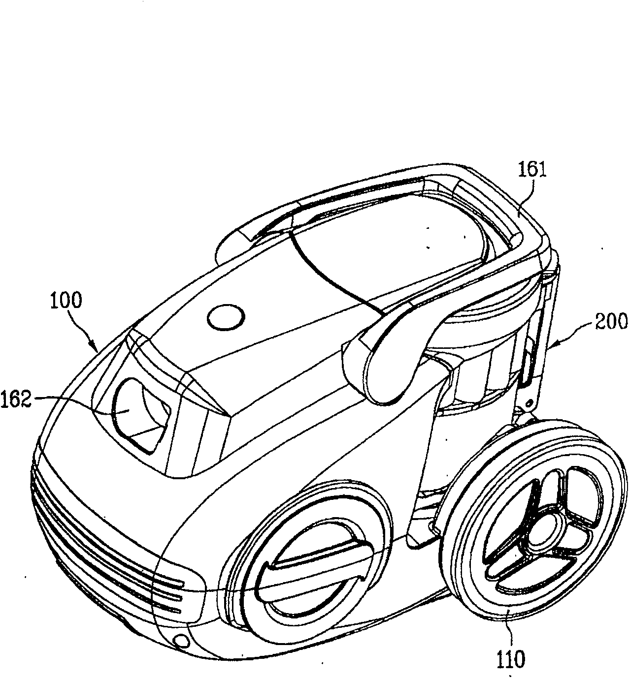
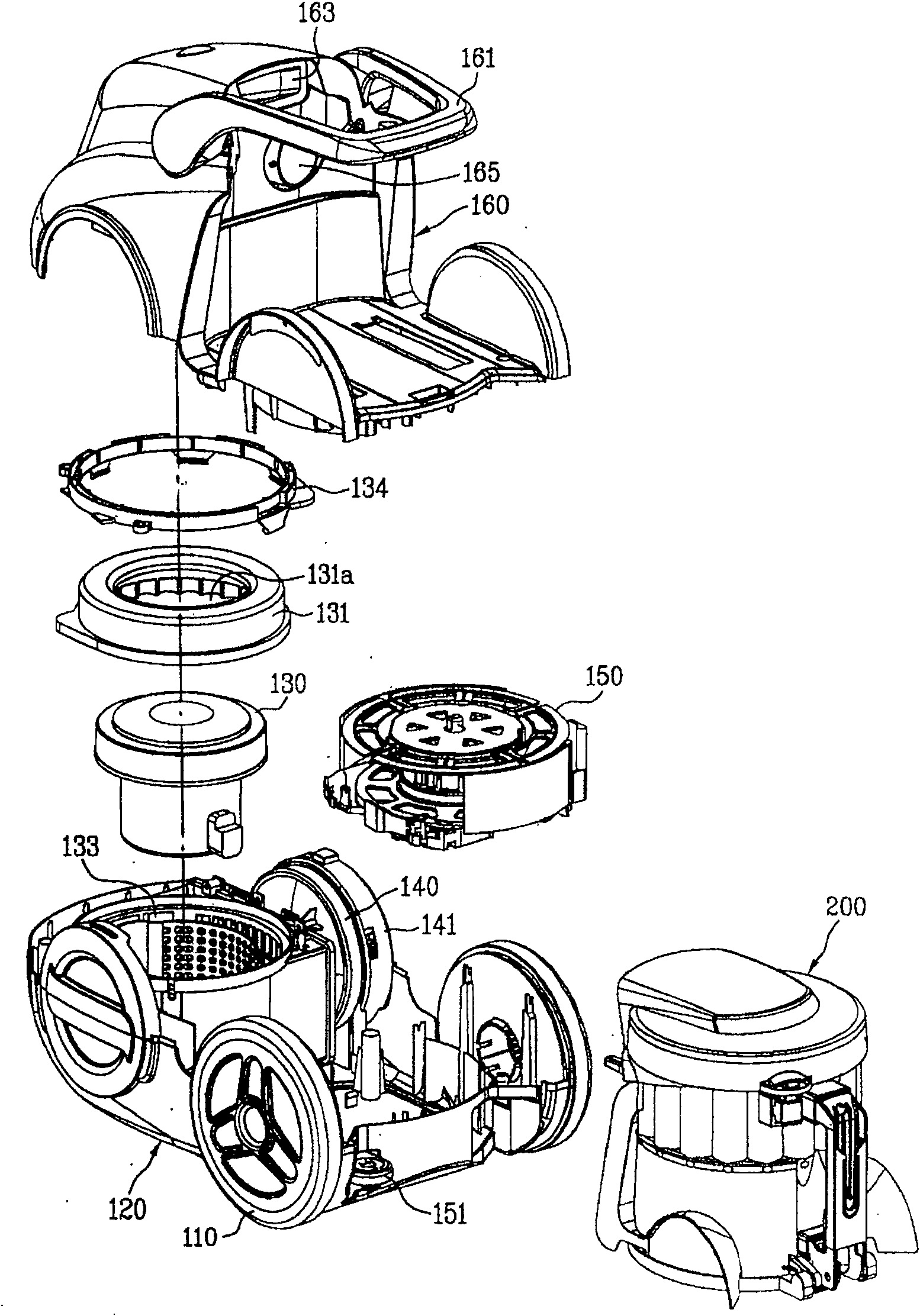
[0037] figure 1 It is a schematic diagram of the appearance of the vacuum cleaner of the present invention. figure 2 It is an exploded schematic diagram of the vacuum cleaner of the present invention.

[0038] Such as figure 1 , 2 As shown, the vacuum cleaner of the present invention includes a suction nozzle that sucks air containing foreign matter while moving along the ground (the figure is omitted), a vacuum cleaner body 100 formed separately from the suction nozzle, and a connection between the suction nozzle and the cleaner body 100, The air sucked by the suction nozzle is guided to the connecting pipe of the vacuum cleaner body 100 (the figure is omitted).

[0039] Here, the bottom surface of the suction nozzle is formed with a suction nozzle suction port (not shown in the figure), which sucks foreign matter and air from th...


PUM


Abstract

The invention relates to a vacuum dust collector which uses the cyclone separation theory to separate the foreigner. Wherein, it comprises a main body with a fan-motor element, an inlet and an outlet;a dust collector combined with the main body to separate the foreigner; the first combiner combined with one side of dust collector; and the second combiner for guiding the collection of dust collector and combining the bottom of collector with the main body. The invention can easily combine or separate the main body and dust collector.

Description

Technical field [0001] The present invention relates to an invention of a vacuum cleaner. In more detail, the present invention relates to a vacuum cleaner that uses the swirling flow principle to separate foreign objects. Background technique [0002] The prior art vacuum cleaner includes a suction nozzle that sucks in foreign matter such as dust on the ground, a vacuum cleaner body with a dust collecting device that separates and collects the foreign matter, and a connection that guides the foreign matter sucked in through the suction nozzle to the vacuum cleaner body. tube. [0003] Here, the main body of the cleaner is provided with an air suction device that generates suction. At a certain position of the main body of the vacuum cleaner, a dust collecting device installation part for installing the dust collecting device is formed. [0004] In addition, the cleaner body is also provided with a cleaner handle for carrying the cleaner body. A wheel is respectively provided on ...

Claims


Application Information

Patent Timeline
Patent Type & Authority Patents(China)
IPC IPC(8): A47L9/10
Inventor 河建镐徐真旭尹昌虎金镇泳李昌勋
Owner LG ELECTRONICS (TIANJIN) APPLIANCES CO LTD
Learn More