
Cutting element having modified surface

A technology of cutting elements and cutting surfaces, applied in the field of manufacturing cutting elements using cutting elements, drill bits and tools equipped with such cutting tools, to achieve the effect of long wear life

Inactive Publication Date: 2014-06-25
DIAMOND INNOVATIONS INC
View PDF6 Cites 2 Cited by
  • Summary
  • Abstract
  • Description
  • Claims
  • Application Information

AI Technical Summary

Problems solved by technology

Although these knives can achieve a certain degree of enhancement in tool durability, there is still a lot of room for improvement

Method used


Image

  • Cutting element having modified surface
  • Cutting element having modified surface
  • Cutting element having modified surface

Examples


Embodiment Construction

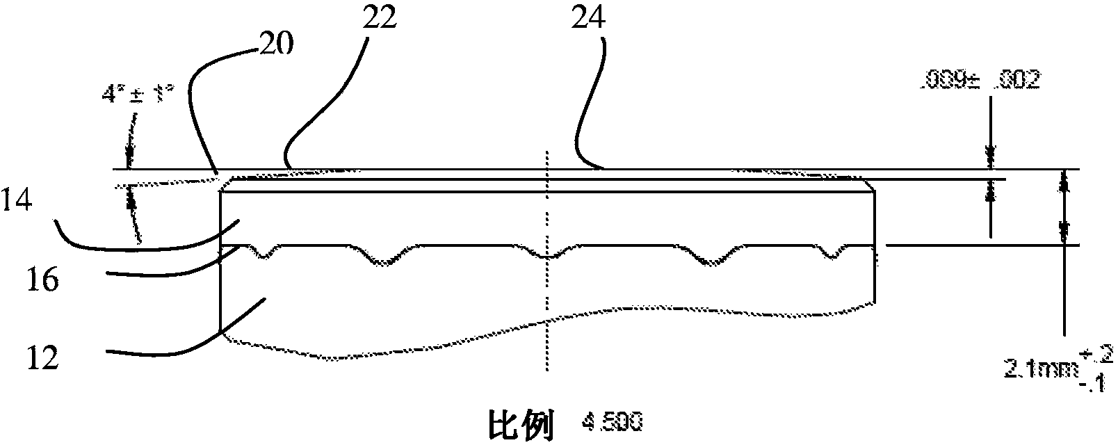
[0054] An improved cutting element is disclosed. The cutting element may be used, but is not limited to, superabrasive tools such as those used in drag bits. Improved cutting elements include reduced chipping, improved wear resistance, and longer tool life, among other improvements. The improvement is at least partially attributable to the addition of a first portion of the cutting face of the cutting element having an angle of about 81° to about 89° relative to the longitudinal axis of the cutting element.

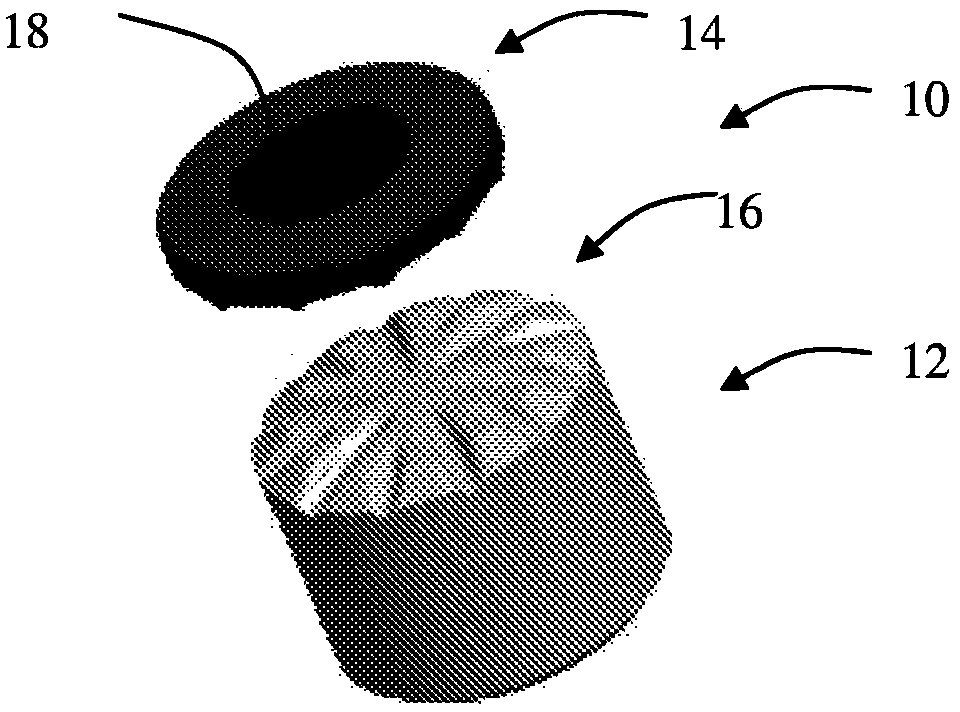
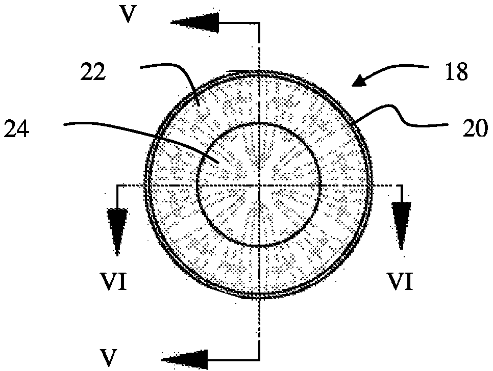
[0055] exist Figure 1 to Figure 6 A first embodiment of a tool comprising an improved cutting face is shown in . Cutting element 10 includes a substrate 12 , a superabrasive layer 14 , and an interface 16 between substrate 12 and superabrasive layer 14 . The superabrasive layer 14 includes a cutting face 18 that forms the top surface of the cutting element 10 . In an embodiment, the cutting face may include a chamfer 20 , a first portion 22 and a second portion 24 . ...


PUM

PropertyMeasurementUnit
Surface roughnessaaaaaaaaaa
Angleaaaaaaaaaa
Surface roughnessaaaaaaaaaa

Abstract

A cutting element including a cutting face and a longitudinal axis passing through the cutting face. The cutting element includes at least a first portion of the cutting face that is angled at an angle of about 81 to about 89 degrees relative to the longitudinal axis of the cutting element. The cutting element can further include a substrate, a superabrasive an interface between the substrate and superabrasive layer. Further, the cutting face is provided with a surface roughness of 40 microinches or less.

Description

technical field [0001] The present disclosure relates to a cutting element, such as a tool for drilling a subterranean formation. More specifically, the present disclosure relates to cutting tools intended to be mounted on a drill bit or other tool for drilling holes in earth or rock, such as may occur in the drilling or enlargement of oil, gas, geothermal, or other subterranean boreholes, and The present disclosure relates to drill bits and tools equipped with such cutting tools. The cutting element includes at least a first portion having an angle of about 81° or about 89° relative to the longitudinal axis. The present disclosure also relates to a method of making a cutting element, and a method of using a cutting element. Background technique [0002] In the discussion of the background that follows, reference is made to certain structures and / or methods. However, the following citations should not be construed as an admission that these structures and / or methods const...

Claims


Application Information

Patent Timeline
IPC IPC(8): E21B10/43
CPCE21B10/5673Y10T408/89E21B10/46E21B7/00B23B51/00B21K5/02
Inventor 大卫·韦恩·布克斯鲍姆内尔·克里斯南
Owner DIAMOND INNOVATIONS INC
Learn More