Eureka AIR delivers breakthrough ideas for toughest innovation challenges, trusted by R&D personnel around the world.

Myoelectric prosthetic control system

A control system and myoelectric technology, applied in prosthetics, medical science, etc., can solve the problems of increasing the mental burden and clumsy movements of users of myoelectric prostheses

Active Publication Date: 2017-03-08
SHENZHEN INST OF ADVANCED TECH CHINESE ACAD OF SCI
View PDF8 Cites 2 Cited by
  • Summary
  • Abstract
  • Description
  • Claims
  • Application Information

AI Technical Summary

Problems solved by technology

This causes clumsy movements in the use of myoelectric prostheses and increases the mental burden of the users of myoelectric prostheses

Method used


Image

  • Myoelectric prosthetic control system
  • Myoelectric prosthetic control system
  • Myoelectric prosthetic control system

Examples


Embodiment Construction

[0035] At present, artificial limbs commercialized at home and abroad include mechanical cable-controlled prostheses, myoelectric prostheses, and myoelectric cable-controlled hybrid prostheses.

[0036] Myoelectric prosthetics use a pair of residual muscles (primary contractor muscles and antagonist muscles) to control a degree of freedom of movement. After limb amputation, the source of myoelectric information is limited. The higher the degree of amputation, the less residual limb muscles, and the more limb movements need to be restored. To control multiple degrees of freedom with a single pair of muscles, myoelectric prosthetics add movement "mode" switching. Switching between "modes" is accomplished by simultaneously "contracting" a pair of muscles or by attaching a switch, which makes the use of myoelectric prosthetics very difficult. Therefore, the traditional myoelectric control method cannot directly realize the multi-degree-of-freedom control of myoelectric prosthesis...


PUM


Abstract

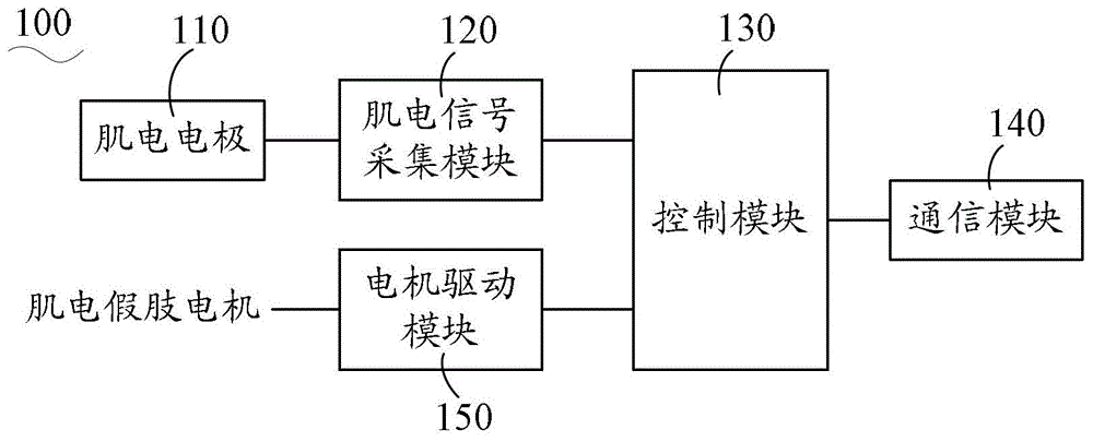
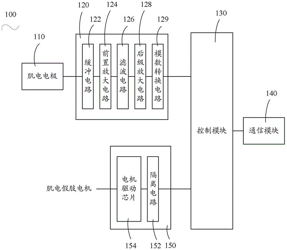
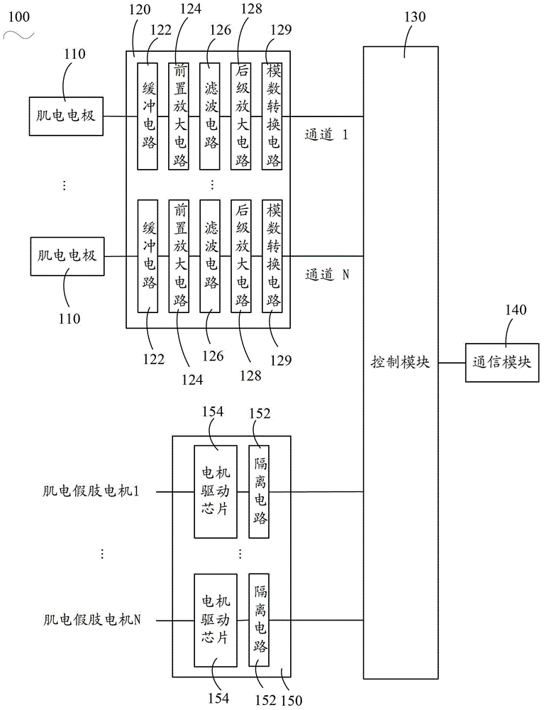
Disclosed is a myoelectric prosthesis control system which comprises a myoelectric prosthesis controller and an upper computer. A user wears a myoelectric prosthesis, the myoelectric prosthesis controller is connected with the upper computer through a communication module, the user prompts according to an action displayed by the upper computer, a phantom limb is utilized to complete corresponding actions, a myoelectric electrode acquires myoelectric signals generated by the surfaces of the limbs of the user, a myoelectric signal acquisition module converts the myoelectric signals to myoelectric data, and a control module transmits the myoelectric data to the upper computer through the communication module. The upper computer performs mode training on the myoelectric data to obtain an action classifier, and sends the action classifier to the control module through the communication module. After the myoelectric prosthesis controller and the upper computer are disconnected and when the user utilizes the phantom limb to execute a certain action, the control module performs action type recognition on the received myoelectric data according to the action classified and outputs a classification result, and a motor drive module drives the myoelectric prosthesis to complete corresponding actions according to the classification result. The myoelectric prosthesis control system is easy and convenient to use and flexible in action.

Description

technical field [0001] The invention relates to artificial limb control technology, in particular to a myoelectric artificial limb control system. Background technique [0002] The myoelectric prosthesis uses the tiny myoelectric potential difference signal as the initial signal to control and manipulate various functions of the myoelectric prosthesis. The myoelectric potential difference signal is measured by electrodes placed on the skin surface of the residual limb to control the muscles. Kinetic energy such as opening, closing and rotation of the electric prosthetic hand. [0003] In the existing myoelectric prosthetic control technology, the myoelectric prosthesis uses a pair of residual muscles (main contractor muscle and antagonist muscle) to control a degree of freedom of movement. After limb amputation, the source of myoelectric information is limited. The higher the degree of amputation, the less residual limb muscles, and the more limb movements need to be restor...

Claims


Application Information

Patent Timeline
Patent Type & Authority Patents(China)
IPC IPC(8): A61F2/72
Inventor 田岚李光林姜乃夫张浩诗朱明星
Owner SHENZHEN INST OF ADVANCED TECH CHINESE ACAD OF SCI
Why Eureka
Eureka Blog
Learn More