
Test system and method used for solar energy module

A technology for a solar module and a test system, which is applied to a test system for solar modules and the field thereof, can solve problems such as structural error, test photoelectric conversion error, etc.

Inactive Publication Date: 2014-07-02
ALL REAL TECH
View PDF1 Cites 1 Cited by
  • Summary
  • Abstract
  • Description
  • Claims
  • Application Information

AI Technical Summary

Problems solved by technology

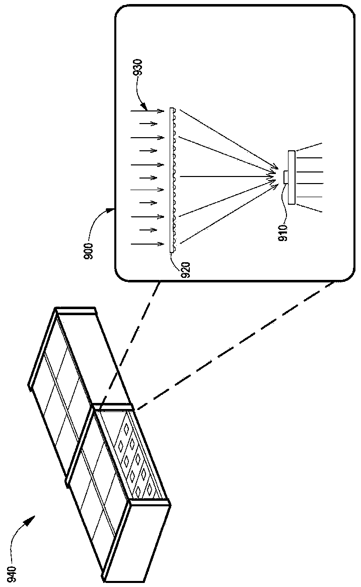
[0004] Theoretically, when the parallel rays 930 of the collimated light source strike the condenser lens group 920 vertically, the solar chip 910 can obtain the maximum conversion efficiency, but structural errors often make it impossible for the parallel rays 930 of the collimated light source to strike the condenser lens vertically On the sheet group 920, there will be a large error when testing the efficiency of photoelectric conversion

Method used


Image

  • Test system and method used for solar energy module
  • Test system and method used for solar energy module
  • Test system and method used for solar energy module

Examples


Embodiment Construction

[0050] The present invention will be further described below in conjunction with the accompanying drawings and specific embodiments, so that those skilled in the art can better understand the present invention and implement it, but the examples given are not intended to limit the present invention.

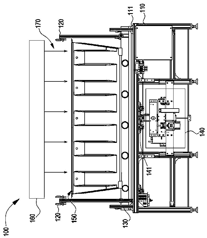
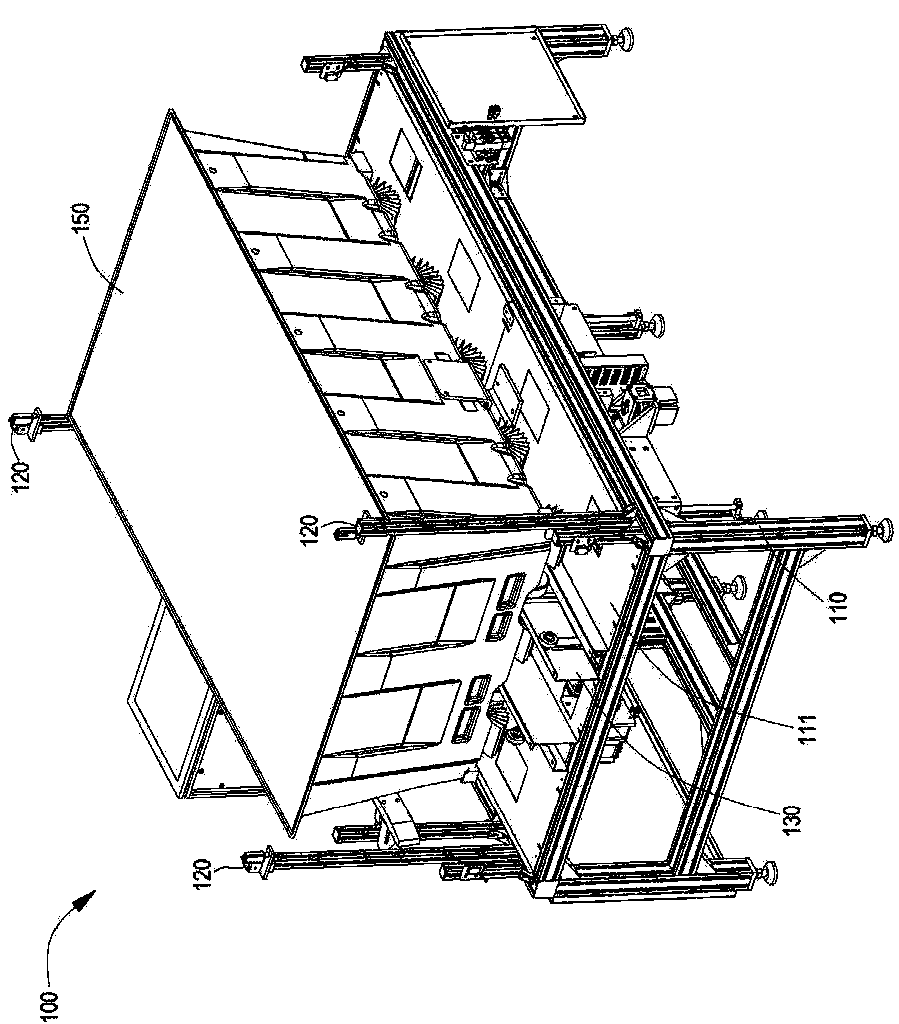
[0051] Such as figure 2 and image 3 As shown, it is a side view and a perspective view of the test system for solar modules of the present invention. Such as Figure 4 Shown is a block diagram of the test system for solar modules of the present invention. The test system 100 includes: a base 110 , a level adjustment mechanism 140 , a light source device 160 , a conveyor belt 130 , a level sensor 120 and a processor 180 . The base 110 includes a desktop 111 with a hole in the center of the desktop 111 .

[0052] The conveyor belt 130 is disposed above the table top 111 of the base 110 and passes through two sides of the hole for transporting the solar module 150 to the level ...


PUM


Abstract

The invention discloses a test system and method used for a solar energy module. The test system comprises a horizontal adjustment mechanism which is used for placing the solar energy module and adjusting the gradient of the solar energy module; a light source device which is used for projecting parallel rays on the solar energy module; and a processor which is electrically connected with the solar energy module and is used for measuring output powers of the solar energy module. The horizontal adjustment mechanism is adjusted for a plurality of times so as to enable the processor to measure a plurality of output powers of the solar energy module and enable the processor to find the maximum value of the output powers.

Description

technical field [0001] The present invention relates to a testing method for a solar module, in particular to a testing system for a solar module, which can be quickly adjusted by the method of the present invention even when the light of the solar module is not perpendicular to the light source device The light to the solar module is perpendicular to the light source device, so as to further find out the maximum output power and quickly complete the next module measurement. Background technique [0002] The use of petroleum fuels is increasing sharply and petroleum is decreasing day by day. With the development of science and technology, the use of solar energy has become common. The practical example of application is the principle of solar cells. [0003] There are many types of solar cells, and the new one is the High Concentration Photovoltaic (HCPV) device, such as figure 1 As shown, the main component of the energy conversion of the high-concentration solar power ge...

Claims


Application Information

Patent Timeline
IPC IPC(8): H02S50/15
CPCY02E10/50
Inventor 郭钟亮赵文平单维峥
Owner ALL REAL TECH
Learn More