Device for measuring wall or ground flatness by lasers

A laser measurement and flatness technology, applied in the field of laser measurement, can solve the problems of inability to meet the flatness control of the measured surface, high cost, poor measurement accuracy and cannot be repaired by the measured surface, etc., to improve the measurement and repair efficiency and easy to carry. , the effect of improving monitoring and trimming efficiency

Active Publication Date: 2014-07-16
STATE GRID CORP OF CHINA +1
View PDF9 Cites 26 Cited by
  • Summary
  • Abstract
  • Description
  • Claims
  • Application Information

AI Technical Summary

Problems solved by technology

[0002] In the prior art, when measuring the flatness of a building, especially for a space to be measured with a relatively small area, it is usually carried out by visual inspection or simple mobile wheel-type measuring tools, such as a ruler, a feeler gauge, etc. The defect of this measurement method is that the operator has high labor intensity, low work efficiency, poor measurement accuracy, and cannot repair the unqualified measured surface in time, especially when the flatness requirement is relatively high, this method cannot satisfy the measured surface. The requirements for surface flatness control. For complex flatness measuring equipment, the cost is high, which limits the occasions of use and affects the improvement of construction quality. There is no related product with compact structure and high detection efficiency in the existing technology.

Method used


Image

  • Device for measuring wall or ground flatness by lasers
  • Device for measuring wall or ground flatness by lasers
  • Device for measuring wall or ground flatness by lasers

Examples


Embodiment 1

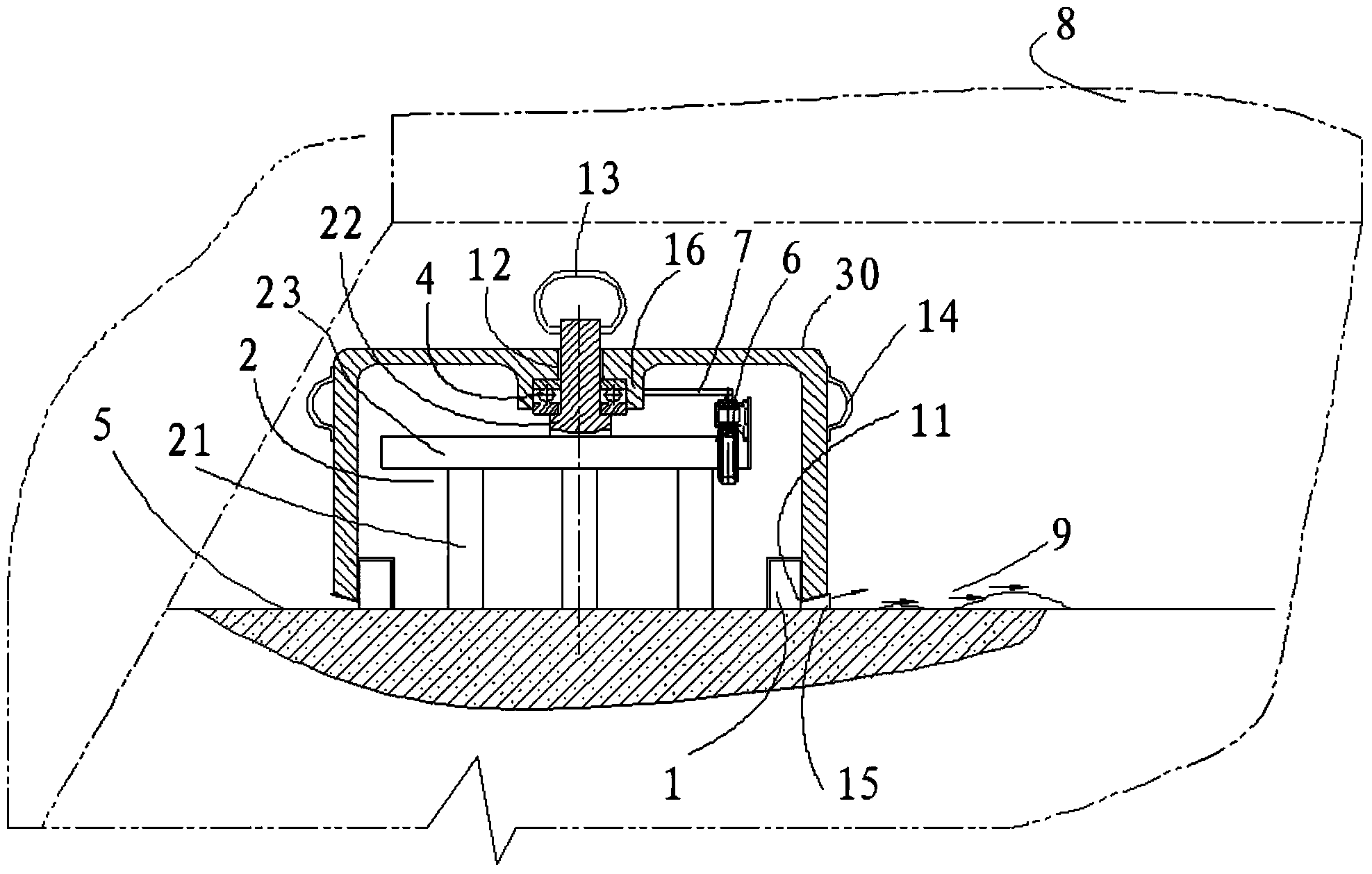
[0028] Such as figure 1 As shown, a device for measuring the flatness of a wall or ground by using a laser includes a base 2 and a laser transmitter 1, the laser transmitter 1 is connected to a laser fixing seat 30, and the lower part of the base 2 is supported on a standard support surface 5 , the standard support surface 5 is a plane with qualified flatness after local leveling and grinding, and the laser emission point 11 of the laser transmitter 1 is located at the lower part of the laser fixing seat 30 and is located in the standard support surface plane 5; A stepped shaft 22 is provided in the middle of the upper part of the base 2, a thrust ball bearing 4 is provided at the small shaft of the stepped shaft 22, a boss 16 is provided on the upper part of the laser transmitter 1, and a stepped hole 12 is provided on the boss 16, so The large hole of the stepped hole 12 cooperates with the thrust ball bearing 4, and the laser emitter 1 rotates around the axis of the stepped...

Embodiment 2

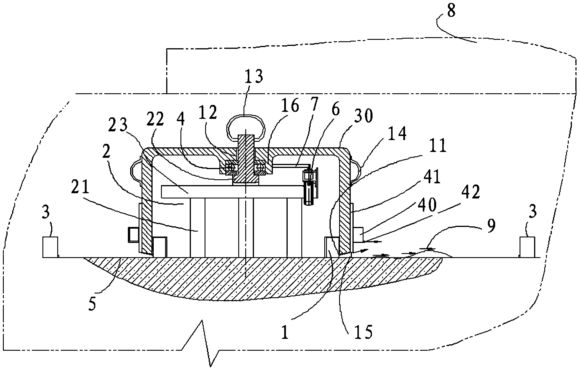
[0035] Such as figure 2 As shown, it is the state when the present invention measures the flatness of the horizontal plane. A laser receiver 3 is arranged around the measured plane, and the receiving point of the laser receiver 3 is located in the standard supporting surface.

[0036] A second laser emitter 40 is provided on the laser mount 30 on the top of the laser emitter 1, and the second laser emitter 40 is connected to the laser mount 30 through a second connecting seat 41 fixed on the outer surface of the laser mount 30. The second connecting seat 41 is provided with a vertical lead screw guide rail, the second laser emitter 40 is provided with a nut, and the second laser emitter 40 moves on the second connecting seat 41 along the guide rail through the cooperation of the lead screw and the nut. The laser beam emitted by the second laser emitter 40 is a straight horizontal parallel light, and the emission port 42 of the second laser emitter 40 is arranged at the bottom...

Embodiment 3

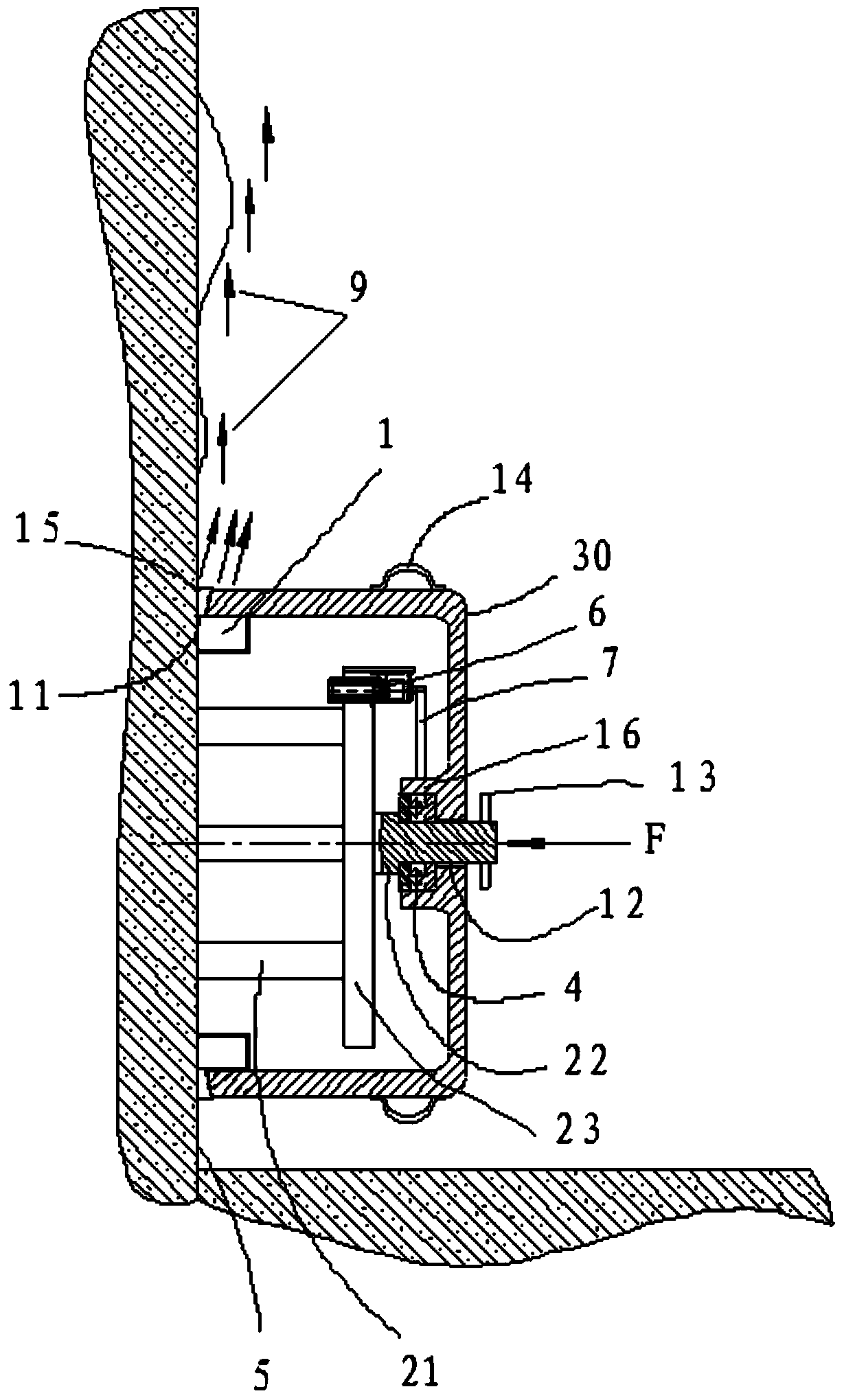
[0039] Such as image 3As shown, it is the state when the present invention measures the flatness of the vertical wall surface. When in use, a force F is applied to the base through the small shaft end of the stepped shaft, so that the supporting feet of the base are in contact with the wall surface, and the whole machine is prevented from falling to the ground. On the ground, turn the laser transmitter to measure the flatness of the measured surface.

[0040] The use method of the present invention: when measuring the flatness of the plane, install the laser emitter and the base, place the base on the ground, use the horizontal air bubble to detect the position of the laser emitter and the placed ground, and adjust the position of the base so that the horizontal air bubble is in the center Position, if the horizontal air bubble deviates from the center position, make the air bubble in the center position by grinding the flatness of the ground at the installation position, or ...


PUM


Abstract

The invention discloses a device for measuring the wall or ground flatness by lasers. The device comprises a base and a laser transmitter, the lower portion of the base is supported on a standard supporting face, the standard supporting face is the plane which is locally leveled and ground, and has the qualified flatness, the laser transmitting point of the laser transmitter is arranged in the plane of the standard supporting face, a stepped shaft is arranged in the middle of the upper portion of the base, a thrust ball bearing is arranged at the position of a small shaft of the stepped shaft, a boss is arranged on the upper portion of the laser transmitter, a stepped hole is formed in the boss, the position of a large hole of the stepped hole is matched with the thrust ball bearing, and the laser transmitter rotates around the axis of the stepped shaft through the thrust ball bearing. The device is simple and compact in laser, a constructor can conveniently conduct wall or ground flatness measurement in the construction process, meanwhile, an inspector can conveniently check and measure the flatness in the inspection and acceptance process, the measured face can be rapidly and accurately measured, and the measuring and repairing efficiency can be improved.

Description

technical field [0001] The invention relates to the technical field of laser measurement, in particular to a device for measuring the flatness of a wall surface or a ground by using a laser. Background technique [0002] In the prior art, when measuring the flatness of a building, especially for a space to be measured with a relatively small area, it is usually carried out by visual inspection or simple mobile wheel-type measuring tools, such as a ruler, a feeler gauge, etc. The defect of this measurement method is that the operator has high labor intensity, low work efficiency, poor measurement accuracy, and cannot repair the unqualified measured surface in time, especially when the flatness requirement is relatively high, this method cannot satisfy the measured surface. The requirements for surface flatness control, for complex flatness measuring equipment, the cost is high, which limits the occasions of use and affects the improvement of construction quality. There is no ...

Claims


Application Information

Patent Timeline
Patent Type & Authority Applications(China)
IPC IPC(8): G01B11/30
Inventor 唐爽苗培青高华伟王吉生李洋单波韩义成王伟陈新刚朱毅
Owner STATE GRID CORP OF CHINA
Why Eureka
Try Eureka