hand dryer

A hand drying and drying chamber technology, applied in the field of hand drying devices, can solve the problems of many cleaning parts, the side cover 109 cannot be maintained, and the maintenance cannot be performed.

Active Publication Date: 2017-10-31
PANASONIC INTELLECTUAL PROPERTY MANAGEMENT CO LTD
View PDF1 Cites 0 Cited by
  • Summary
  • Abstract
  • Description
  • Claims
  • Application Information

AI Technical Summary

Problems solved by technology

Therefore, maintenance cannot be performed without removing the side cover 109
[0007] As mentioned above, the conventional hand dryer 100 is provided with the side cover 109 for maintenance on the side side of the drying chamber 103, so there is a problem that maintenance cannot be performed when the installation space is narrow.
In addition, there are many cleaning parts, and there is a problem that maintenance cannot be easily performed.

Method used


Image

  • hand dryer
  • hand dryer
  • hand dryer

Examples


Embodiment approach 1

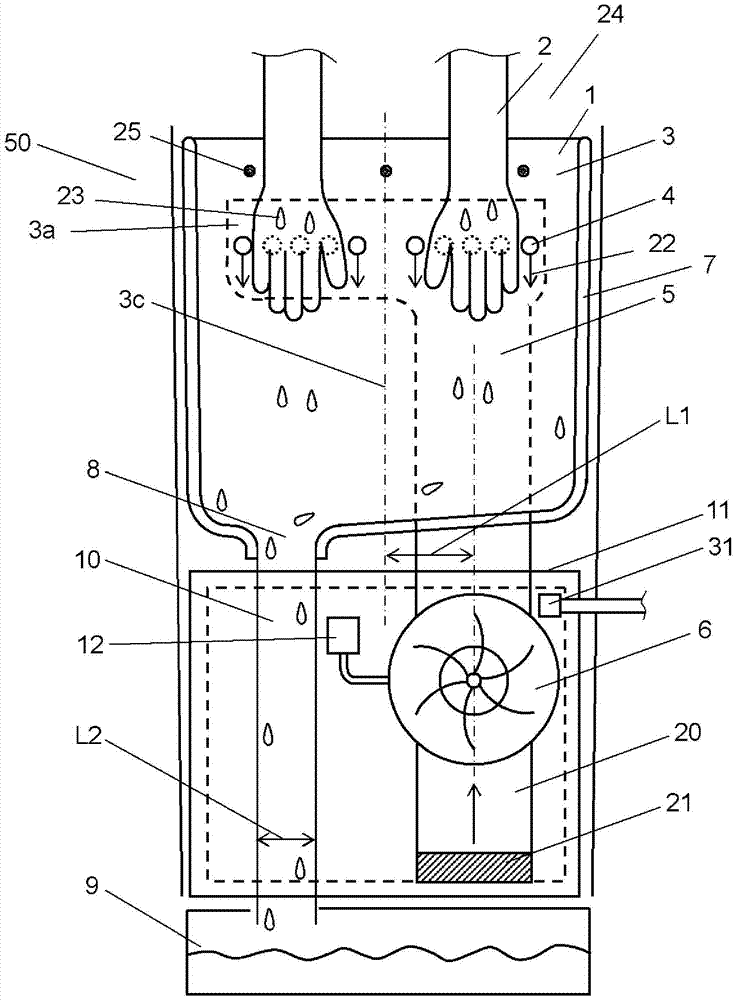
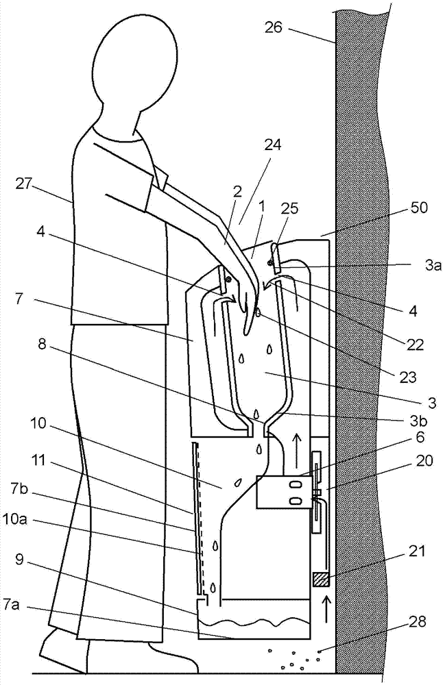
[0022] figure 1 It is a front view of the hand dryer according to Embodiment 1 of the present invention, figure 2 is a side view of the hand dryer. Such as figure 1 , figure 2 As shown, in the hand drying device 50 , the hand 2 is inserted into the drying chamber 3 from the insertion port 1 , and the water droplets 23 attached to the wet hand 2 are blown away to dry the hand 2 . The hand dryer 50 is attached to the indoor wall 26 of a toilet or the like. Here, the insertion opening 1 is provided in the upper part of the box-shaped main body 7 .

[0023] The air blower 6 which sends out the high-pressure air 22 of 0.5kPa-15kPa from the nozzle 4 via the discharge air path 5 is built in the lower part of the main body 7 of the hand dryer 50. As shown in FIG. The blower 6 installed inside the main body 7 as described above is a centrifugal blower in which a turbine-type impeller is attached to a rotating shaft of a motor. The drying chamber 3 opens toward the outside 24 ...

Embodiment approach 2

[0035] In Embodiment 2 of the present invention, the same reference numerals are assigned to the same constituent elements as in Embodiment 1, detailed description thereof will be omitted, and only different points will be described.

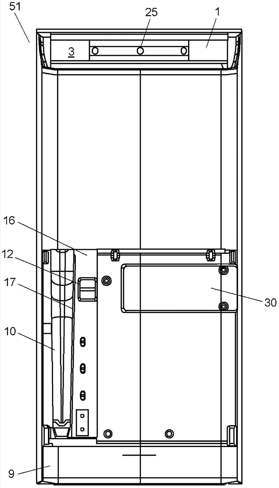
[0036] image 3 It is the front view of the hand dryer of Embodiment 2 of this invention, Figure 4 is a side sectional view of the hand dryer. image 3 is the lower part of the hand dryer 51 figure 1 The state in which the front surface cover 11 is removed is shown. in addition, Figure 4 The cross-sectional position of is the position where the drainage channel 10 is divided into two parts in the longitudinal direction.

[0037] Such as image 3 As shown, when the front cover 11 is removed, the drain path 10 is exposed at the left end when viewed from the front. Furthermore, a switch unit 16 is provided adjacent to the drain path 10 .

[0038] A partition rib 17 is provided between the drain path 10 and the switch portion 16 including th...


PUM


Abstract

The drying chamber (3) of the hand drying device (50) includes an insertion port (1), a nozzle (4) and a drain port (8). In addition, a drain pan (9) for accumulating water droplets (23) is provided at the bottom of the main body (7), and the drainage path (10) connecting the drain pan (9) and the drain port (8) is arranged along the side of the main body (7). The front surface cover (11) of the front surface is provided. Moreover, when the front surface cover (11) is removed, the drain path (10) and the power switch (12) are simultaneously exposed.

Description

technical field [0001] The present invention relates to hand dryers. Background technique [0002] Conventional hand dryers are used to dry hands wetted by washing with water, and are used in washrooms, toilets, kitchens, and the like. And the side panel for maintenance for confirming a drain path is provided in the side surface side of the drying chamber of a hand dryer. (For example, refer to Patent Document 1). [0003] Figure 6 It is an exploded perspective view of a conventional hand dryer, Figure 7 It is a sectional view of the drying chamber of this hand drying apparatus. Such as Figure 6 , 7 As shown, the conventional hand dryer 100 has a blower (not shown) inside, and the high-pressure air sent from the blower is blown out into the drying chamber 103 provided above. Then, the high-pressure air blows away the water droplets attached to the hand 102 inserted into the drying chamber 103 . [0004] The drying chamber 103 has an insertion port 101 that opens upw...

Claims


Application Information

Patent Timeline
Patent Type & Authority Patents(China)
IPC IPC(8): A47K10/48
CPCA47K10/48
Inventor 新崎幸司古山孝
Owner PANASONIC INTELLECTUAL PROPERTY MANAGEMENT CO LTD
Why Eureka
Try Eureka