Safety guide device

A technology of safety guidance and luminous lines, which is applied to display devices, signal devices, visible signal devices, etc., can solve the problems of point-like luminous safety guidance facilities that cannot play a continuous guidance function, command confusion, loss, etc., and achieve mobile action Clear and smooth, clear guidance, simple and reasonable structure

Inactive Publication Date: 2014-08-06
SHENZHEN ZHUIGUANG ELECTRONICS TECH CO LTD
View PDF8 Cites 1 Cited by
  • Summary
  • Abstract
  • Description
  • Claims
  • Application Information

AI Technical Summary

Problems solved by technology

In the corridors of large buildings, especially in mine tunnels and large complex places, these point-like luminescent safety guidance facilities cannot provide continuous guidance functions, and are likely to cause command confusion and cause further losses

Method used


Image

  • Safety guide device
  • Safety guide device
  • Safety guide device

Examples


no. 1 example

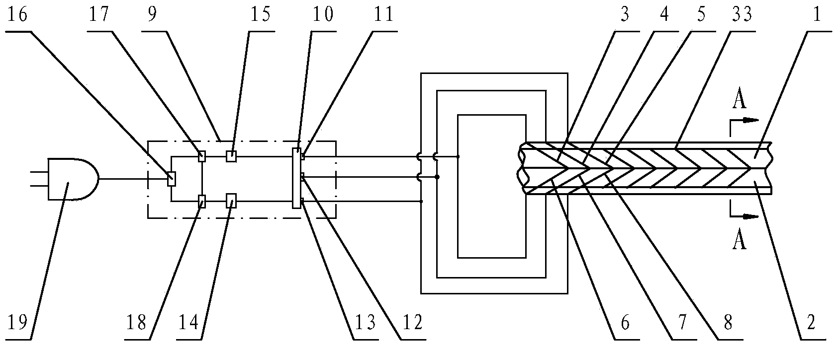
[0042] see Figure 1-Figure 2 , the safety guidance device includes a luminous line and a multi-channel AC driver 9 for driving the luminous line to work. There are more than two luminous lines, and the luminous lines arranged front and back or arranged side by side form an arrow shape.

[0043] There are more than two luminous lines with the same luminous color. Alternatively, there are more than two luminous lines with similar luminous colors.

[0044] In this embodiment, only the outward part of the luminescent line is coated with a mixed layer of luminescent powder and binder and a metal transparent electrode layer. The insulating medium coated on the metal base in the luminous line is composed of titanium dioxide or barium carbonate and polyurethane or high-resolution glue mixture.

[0045] The light-emitting lines include a first light-emitting line 3 , a second light-emitting line 4 , a third light-emitting line 5 , a fourth light-emitting line 6 , a fifth light-emitt...

no. 2 example

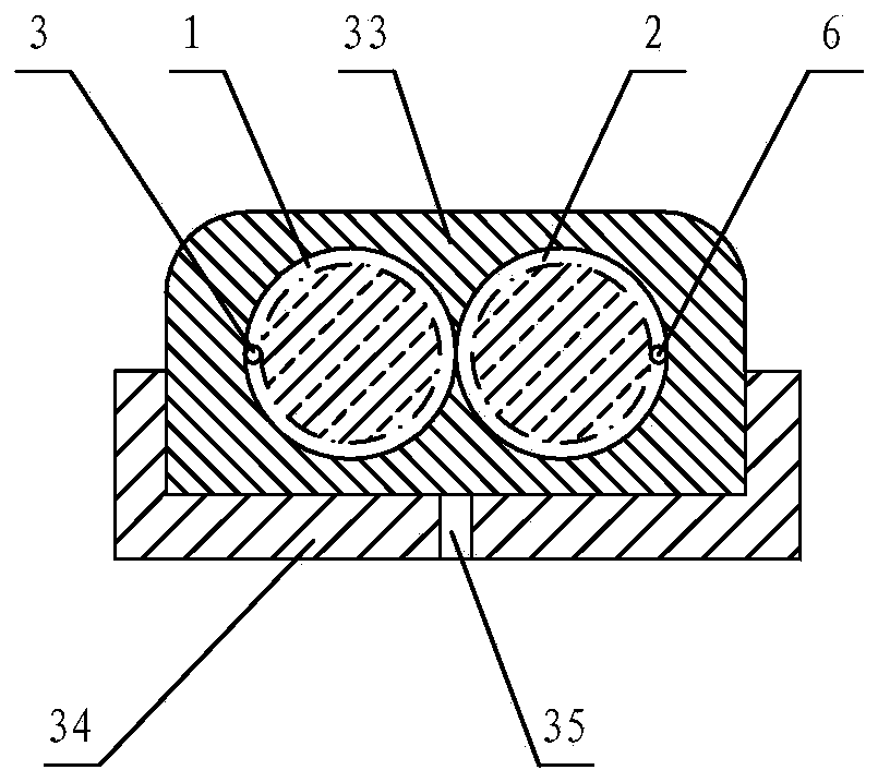
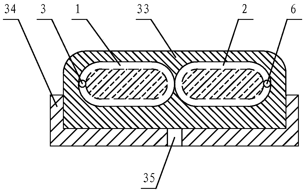
[0057] see image 3 , in this embodiment, the cross-sectional structure of the first sequentially segmented lighting cable 1 and the second sequentially segmented lighting cable 2 can be as follows image 3 Oval or oblong as shown.

[0058] Refer to the first embodiment for the rest of the undescribed parts, and will not repeat them here.

no. 3 example

[0060] see Figure 4-Figure 5 , in this embodiment, the light emitting lines include the seventh light emitting line 41, the eighth light emitting line 42 and the ninth light emitting line 43, more than three arrow grooves 45 are sequentially arranged on the second mounting board 40, the seventh light emitting line 41 is embedded in the first arrow groove 45 , the eighth light emitting line 42 is embedded in the second arrow groove 45 , and the ninth light emitting line 43 is embedded in the third arrow groove 45 .

[0061] The second mounting plate 40 is provided with six arrow grooves 45 in sequence, and the seventh light emitting line 41 embedded in the first arrow groove 45 is embedded in the fourth arrow groove 45 after turning back, and embedded in the fourth arrow groove 45. The eighth light emitting line 42 in the first arrow groove 45 is embedded in the fifth arrow groove 45 after being turned back, and the ninth light emitting line 43 embedded in the third arrow groo...


PUM


Abstract

A safety guide device comprises two or more light emitting lines and a multi-path alternating current driver driving the light emitting lines to work. The light emitting lines which are arranged front and back or arranged left and right in parallel are of an arrow shape. The light emitting lines include the first light emitting line, the second light emitting line, the third light emitting line, the fourth light emitting line, the fifth light emitting line and the sixth light emitting line, wherein the first light emitting line, the second light emitting line and the third light emitting line rotate rightwards to be intertwisted or rotate rightwards to be sequentially wound around a first mandrel or a first core line so as to form a first cable emitting light sequentially section by section; the fourth light emitting line, the fifth light emitting line and the sixth light emitting line rotate leftwards to be intertwisted or rotate leftwards to be sequentially wound around a second mandrel or a second core line so as to form a second cable emitting light sequentially section by section; the first cable emitting light sequentially section by section and the second cable emitting light sequentially section by section are arranged left and right in parallel; the first light emitting line and the fourth light emitting line form an arrow. The safety guide device has the advantages of being simple and reasonable in structure, flexible in operation, clear in guiding and wide in application range.

Description

technical field [0001] The invention relates to a safety guide device. Background technique [0002] Safety exits are generally installed in all buildings, halls, halls and various public facilities. These safety exits are basically equipped with fire safety indicators such as emergency lights that automatically start when the power is off. These fire safety indicators are all point-shaped lights Safety guidance facilities. In the corridors of large buildings, especially in mine tunnels and large complex places, these point-like luminescent safety guidance facilities cannot play a continuous guidance function, and are likely to cause command confusion and cause further losses. [0003] Chinese Patent Document No. CN1916679B disclosed on January 19, 2011 an electroluminescent cable that emits light segment by segment, including a luminescent core wire, a guiding wire and a transparent outer layer, wherein at least two groups of luminescent core wires are twisted to each othe...

Claims


Application Information

Patent Timeline
Patent Type & Authority Applications(China)
IPC IPC(8): G09F13/22
CPCG08B7/066G08B5/36G08B7/062
Inventor 殷峥凯
Owner SHENZHEN ZHUIGUANG ELECTRONICS TECH CO LTD
Why Eureka
Try Eureka