
Light compensating method and electronic equipment

An electronic device and light supplement technology, applied in the multimedia field, can solve the problem of inaccurate image supplement light

Active Publication Date: 2014-08-06
LENOVO (BEIJING) LTD
View PDF5 Cites 12 Cited by
  • Summary
  • Abstract
  • Description
  • Claims
  • Application Information

AI Technical Summary

Problems solved by technology

[0006] Embodiments of the present invention provide a method and electronic equipment for supplementing light, which are used to solve the technical problem in the prior art that the supplementary light for images is not accurate enough

Method used


Image

  • Light compensating method and electronic equipment
  • Light compensating method and electronic equipment
  • Light compensating method and electronic equipment

Examples


Embodiment 1

[0065] Embodiment 1 of the present application provides a method for supplementing light. The method is applied to electronic equipment, and the electronic equipment includes a projection module and an image acquisition module. The electronic equipment is, for example, a notebook computer, a mobile phone, a video camera, and the like.

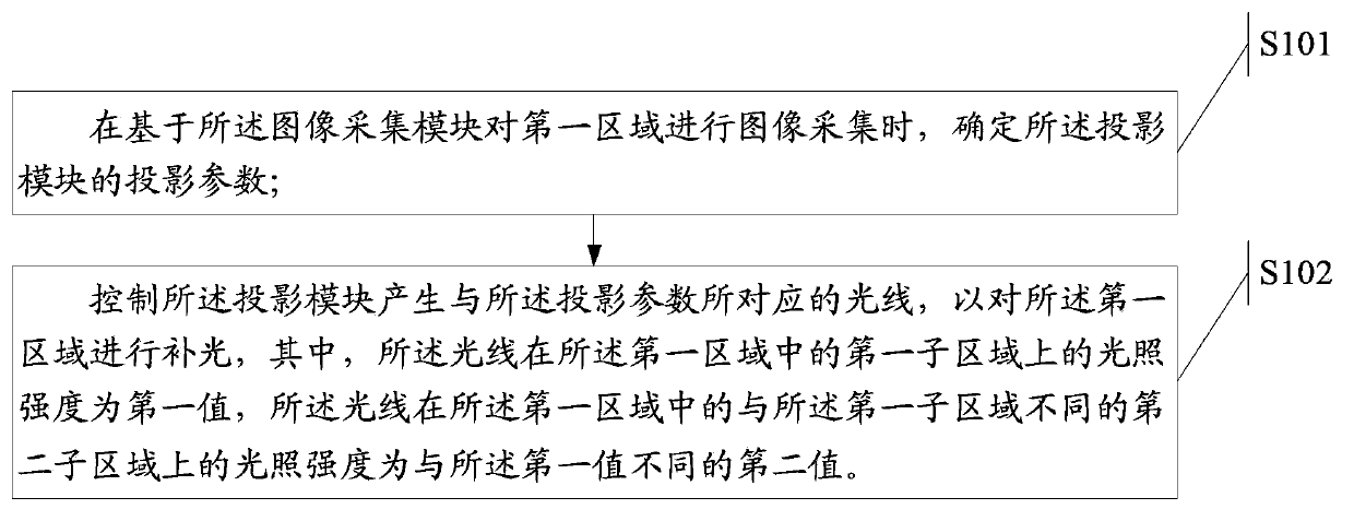
[0066] Please refer to figure 1 , the method for supplementing light comprises the steps of:

[0067] Step S101: When performing image acquisition on the first area based on the image acquisition module, determine the projection parameters of the projection module;

[0068] Step S102: Control the projection module to generate light corresponding to the projection parameters, so as to supplement light on the first area, wherein the light illuminates the first sub-area in the first area The intensity is a first value, and the illumination intensity of the light on a second sub-area different from the first sub-area in the first area is a second ...

Embodiment 2

[0100]Embodiment 2 of the present application provides an electronic device, the electronic device includes a projection module and an image acquisition module, and the electronic device is, for example, a notebook computer, a mobile phone, a video camera, and the like.

[0101] Please refer to Figure 5 , the electronic device also includes the following structure:

[0102] A determination module 501, configured to determine the projection parameters of the projection module when the first area is captured based on the image capture module;

[0103] The control module 502 is configured to control the projection module to generate light corresponding to the projection parameters, so as to supplement the light in the first area, wherein the light is in the first sub-area of ​​the first area The illumination intensity on the light is a first value, and the illumination intensity of the light on a second sub-area different from the first sub-area in the first area is a second va...


PUM


Abstract

The invention discloses a light compensating method and electronic equipment. The light compensating method is applied into the electronic equipment. The electronic equipment comprises a projection module and an image acquiring module. The light compensating method includes determining projection parameters of the projection module when the image acquiring module acquires images of a first area; controlling the projection module to generate light corresponding to the projection parameters so as to compensate light of the first area, wherein the illumination intensity of the light in a first subrange in the first area is a first value, and the illumination intensity of the light in a second subrange different from the first subrange in the first area is a second value different from the first value.

Description

technical field [0001] The invention relates to the field of multimedia technology, in particular to a light supplement method and electronic equipment. Background technique [0002] With the continuous development of science and technology, electronic technology has also developed rapidly, and there are more and more types of electronic products. People also enjoy various conveniences brought by the development of science and technology. Among them, people can Collect various images. [0003] In the prior art, when collecting images through a camera, in some cases, it is necessary to supplement the collected images with a supplementary light so as to ensure that the collected images will not be too dark. [0004] In the process of implementing the technical solutions of the embodiments of the present application, the inventors of the present application at least found the following technical problems in the prior art: [0005] Because in the prior art, when the image is s...

Claims


Application Information

Patent Timeline
Patent Type & Authority Applications(China)
IPC IPC(8): H04N5/74
Inventor 李凡智刘旭国
Owner LENOVO (BEIJING) LTD
Learn More