

Operation use platform for ophthalmology department of children
An ophthalmology and surgery technology, applied in the field of operation platform for children's ophthalmology, can solve the problems of inability to adjust the height, children are prone to hyperactivity, and the shadowless lamp cannot meet the precise requirements, and achieves the effect of ensuring safety and convenient operation.
- Summary
- Abstract
- Description
- Claims
- Application Information
AI Technical Summary
Problems solved by technology
Method used
Image

Examples
Embodiment 1
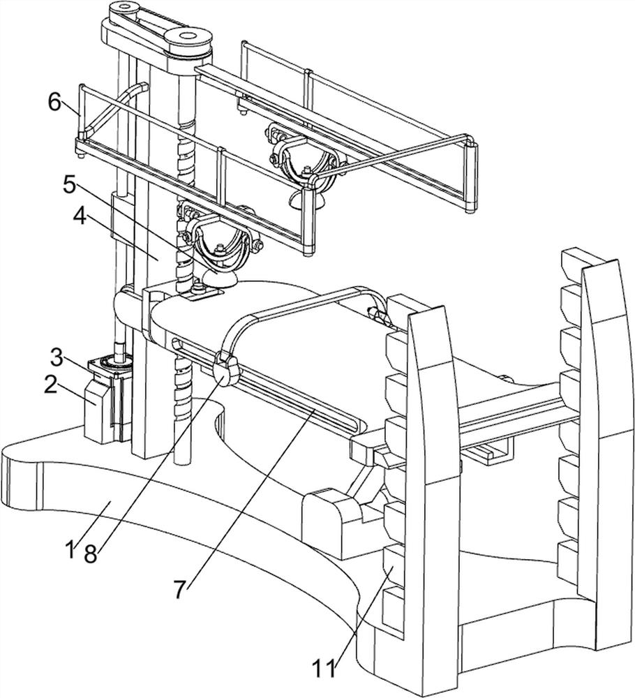
[0080] A surgical use platform for pediatric ophthalmology, such as figure 1 As shown, it includes a base 1, a fixed seat 2, a servo motor 3, a lifting mechanism 4 and a translation mechanism 7, the left side of the top of the base 1 is provided with a fixed seat 2, the inside of the fixed seat 2 is provided with a servo motor 3, and the left side of the top of the base 1 A lifting mechanism 4 is provided, and a translation mechanism 7 is provided between the top of the base 1 and the lifting mechanism 4 .
[0081] Before performing ophthalmic surgery, the medical personnel first start the servo motor 3 to work, the servo motor 3 drives the lifting mechanism 4 to work, the lifting mechanism 4 drives the translation mechanism 7 to adjust the position, after the adjustment is completed, turn off the servo motor 3, and then the child can Lying on the translation mechanism 7, medical personnel can perform ophthalmic surgery on it. After the operation, the servo motor 3 can be star...
Embodiment 2
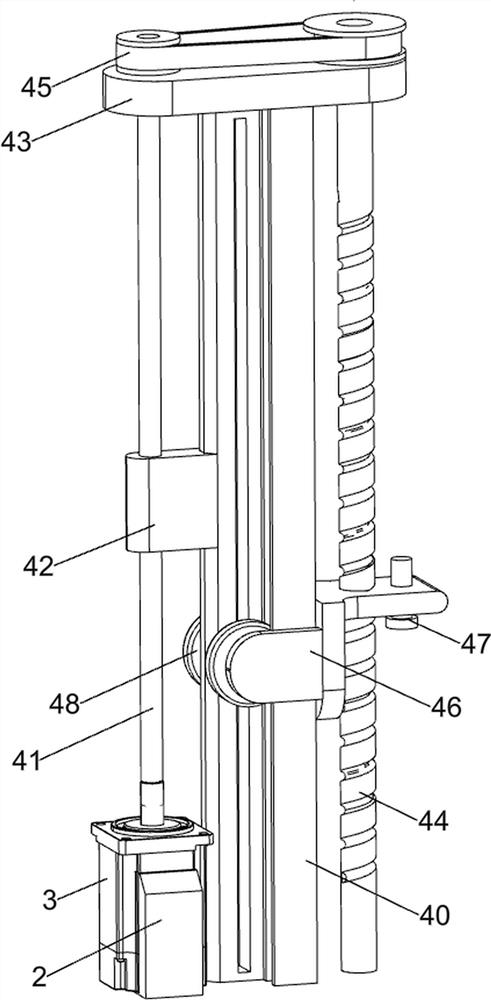
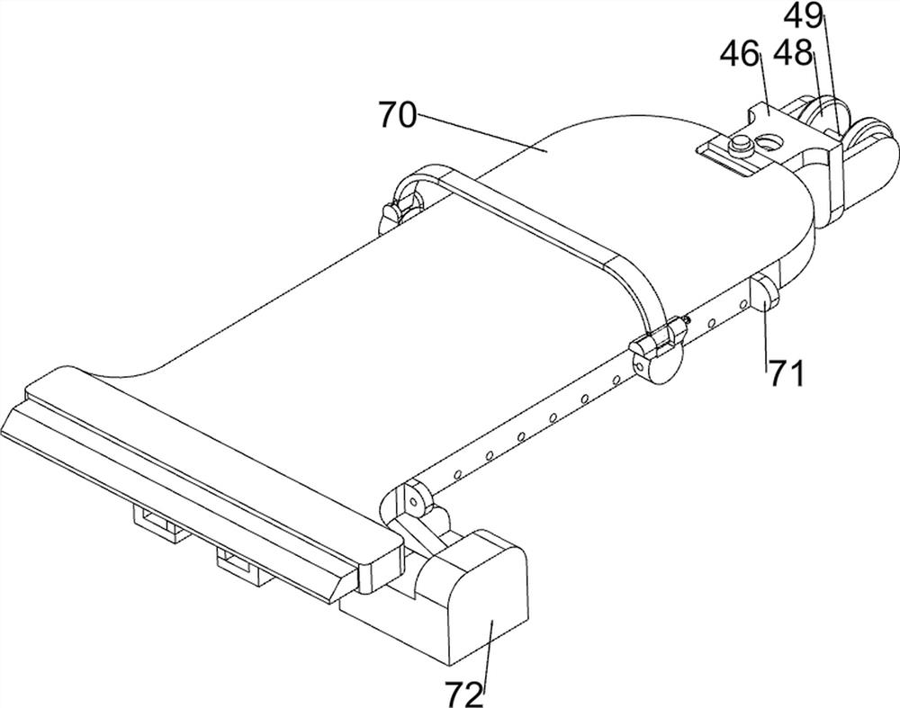
[0083] On the basis of Example 1, such as figure 2 , image 3 , Figure 6 and Figure 7 As shown, the lifting mechanism 4 includes a support frame 40, a rotating shaft 41, a fixed block 42, a first connecting plate 43, a screw mandrel 44, a pulley assembly 45, a first connecting frame 46, a first connecting rod 47, a first roller 48 and The second connecting rod 49, the left side of the top of the base 1 is provided with a support frame 40, the output end of the servo motor 3 is provided with a rotating shaft 41, the support frame 40 is provided with a fixed block 42, the fixed block 42 is rotationally connected with the rotating shaft 41, and the support frame 40 The top is provided with a first connecting plate 43, and the rotating shaft 41 is rotatably connected with the first connecting plate 43. The left side of the base 1 is rotatably provided with a screw 44, and the screw 44 is rotatably connected with the first connecting plate 43. The rotating shaft 41 is connecte...
Embodiment 3
[0087] On the basis of Example 2, such as Figure 4 , Figure 5 , Figure 7 and Figure 8 As shown, an adjustment mechanism 6 is also included, and the adjustment mechanism 6 includes a fixed frame 60, a second connecting plate 61, a guide plate 62, a fourth connecting rod 63, a guide block 64, a second fixing ring 65, and a third connecting plate 66 , the second connecting frame 67, the first guiding ring 68, the second guiding ring 69, the fifth connecting rod 610 and the third fixing ring 611, the front and rear sides of the support frame 40 top are all provided with fixing brackets 60, the first connecting plate 43 The right side is provided with a second connecting plate 61, the end of the fixed frame 60 is provided with a guide plate 62, the right side of the top of the guide plate 62 is provided with a guide block 64, and the fixed frame 60 on the same side is connected to the guide plate 62 in a sliding manner. There is a fourth connecting rod 63, the bottom of the ...
PUM
 Abstract
Description
Claims
Application Information