Sheet trimming machine

An edge trimming machine and plate technology, which is applied to metal sawing equipment, sawing machine devices, metal processing equipment and other directions, can solve the problems of low processing accuracy, poor sawing stability, affecting processing accuracy, etc., and achieves high processing precision. Eliminate accumulated errors and have good working stability

Active Publication Date: 2016-08-17
浙江晨雕机械有限公司
View PDF13 Cites 0 Cited by
  • Summary
  • Abstract
  • Description
  • Claims
  • Application Information

AI Technical Summary

Problems solved by technology

[0004] However, the above-mentioned common edge trimmer has the following problems in the edge trimming process. One, the saw beam will vibrate when it moves on the saw beam support frame, thereby affecting the work of the circular saw blades doing cutting motion at the same time, reducing the impact of the circular saw. The sawing stability and sawing accuracy of the device, the quality of processed products is low
2. Since the workpiece material is processed by rotation and compression of the downward-pressing compression device, the workpiece material is easy to loosen during rotation and compression, resulting in processing errors and affecting the processing accuracy, and the structure is not compact, and it is inconvenient to clamp the workpiece
3. The protective cover around the base needs to have enough height to prevent the sawdust from splashing out, but the height of the protective cover is limited by the height of the saw beam support frame. The improvement of the side of the saw beam support frame will cause the circular saw The distance between the circular saw blade in the device and the saw beam increases, and the greater the distance increases, the greater the vibration of the circular saw blade during processing, the worse the sawing stability, and the lower the processing accuracy

Method used


Image

  • Sheet trimming machine
  • Sheet trimming machine
  • Sheet trimming machine

Examples


Embodiment Construction

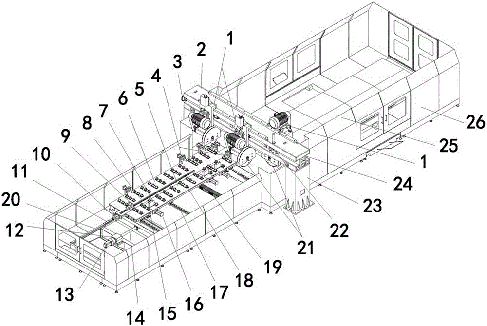
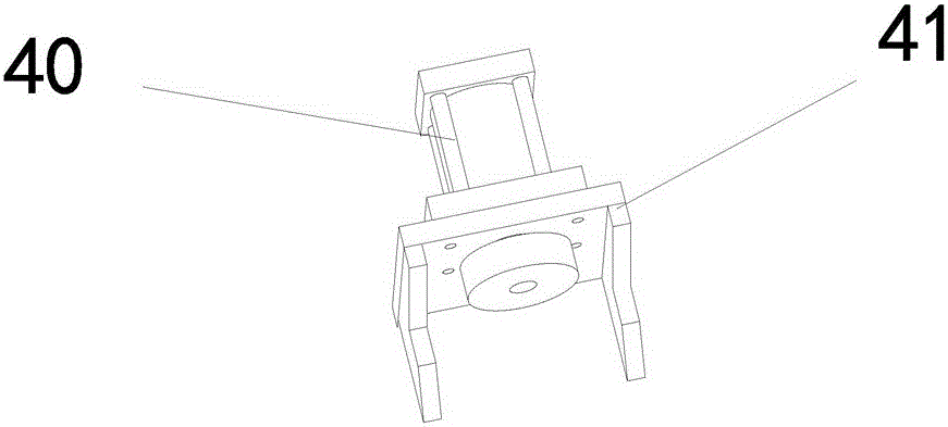
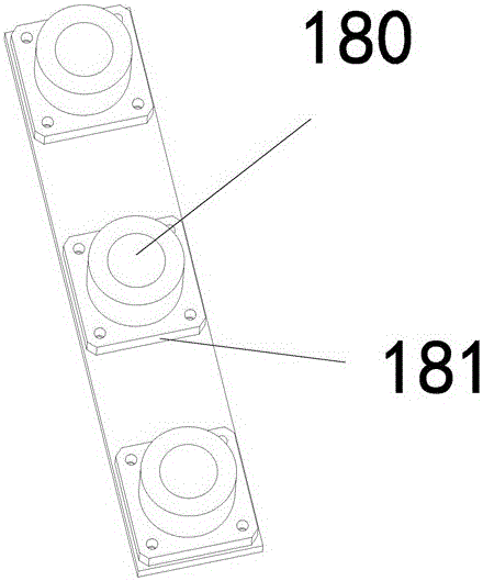
[0019] Description of drawings: 1-circular saw device, 2-saw beam, 3-adjusting hand wheel, 4-workpiece clamp, 5-rear workbench, 6-front workbench, 7-movable splint, 8- Rack, 9-movable pliers, 10-clamping cylinder, 11-lower guide rail, 12-motor seat, 13-servo motor, 14-screw, 15-adjusting driving device, 16-clamping cylinder, 17-upper Guide rail, 18-longan device, 19-sheath, 20-base, 21-circular saw blade, 22-servo motor, 23-column, 24-saw beam groove, 25-folding bevel, 26-protective cover, 40-clamping oil cylinder, 41-fixed clip seat, 180-ball, 181-ball seat.

[0020] Such as figure 1 As shown, a board trimming machine includes a base 20, a workbench, a saw beam 2 and a circular saw device 1, a movable circular saw device 1 is provided on the right side of the saw beam 2, and a movable circular saw device 1 is provided on the left side of the saw beam 2. Two movable circular saw devices 1 are provided; the saw beam 2 is connected with the tops of two columns 23 to form a gan...


PUM


Abstract

The invention discloses a plate trimming machine, which comprises a base, a workbench, a saw beam and disk saw devices, wherein one movable disk saw device is arranged on the right side of the saw beam; two movable disk saw devices are arranged on the left side of the saw beam. The plate trimming machine is characterized in that the saw beam is connected with the top ends of two upright posts to construct a gantry; the base below the saw beam extends from the left side and the right side of the saw beam, and is separated from the two upright posts; a movable workbench and a main driving device connected with the workbench are arranged on the base; workpiece clamping tongs for clamping in the horizontal direction are arranged on front side, back side, left side and right side of the workbench; a plurality of gantry hole devices for supporting workpieces in a rolling way are arranged in an arrayed manner on the workbench respectively; each gantry hole device consists of a ball and a ball base. The plate trimming machine is high in trimming accuracy, high in stability and convenient for machining.

Description

technical field [0001] The invention relates to a metal sawing device, in particular to a board edge trimmer suitable for high-precision sawing. Background technique [0002] Today, the aerospace industry is developing rapidly, and the processing accuracy of the widely used aluminum alloy sheets is constantly improving. Because many aluminum alloy sheet materials for aerospace are mainly formed by casting, then sliced ​​by sawing machine tools, and then trimmed by edge trimmers. Therefore, the edge trimming of the edge trimmer will directly affect the shape processing accuracy of the sheet material. [0003] The common trimming machine of prior art usually comprises base, workbench, saw beam, circular saw device and pressing device, and described circular saw device is all made up of circular saw blade, driving motor, sliding support plate, servo motor and Composition of drive screw. The four sides of the base are fixed with a saw beam support frame, the four walls of the...

Claims


Application Information

Patent Timeline
Patent Type & Authority Patents(China)
IPC IPC(8): B23D47/04B23D47/02B23D47/00
Inventor 卢建飞张小杰
Owner 浙江晨雕机械有限公司
Why Eureka
Try Eureka