Side-direction inlet light type annular light-emitting device

A light-emitting device, a ring-shaped technology, applied in lighting devices, optics, light guides, etc., can solve the problems of glare and light leakage at the incoming light, and the ring light source cannot achieve uniform light output, and achieve the effect of a uniform ring light source.

Active Publication Date: 2014-08-13
苏州茂立光电科技有限公司
View PDF4 Cites 16 Cited by
  • Summary
  • Abstract
  • Description
  • Claims
  • Application Information

AI Technical Summary

Problems solved by technology

[0003] The purpose of the present invention is to provide a side-light-incidence ring-shaped light-emitting device to solve the problems in the prior art that the ring-shaped light source cannot achieve uniform light output and is prone to glare and light leakage at the light-incoming place.

Method used


Image

  • Side-direction inlet light type annular light-emitting device
  • Side-direction inlet light type annular light-emitting device
  • Side-direction inlet light type annular light-emitting device

Examples


Embodiment 1

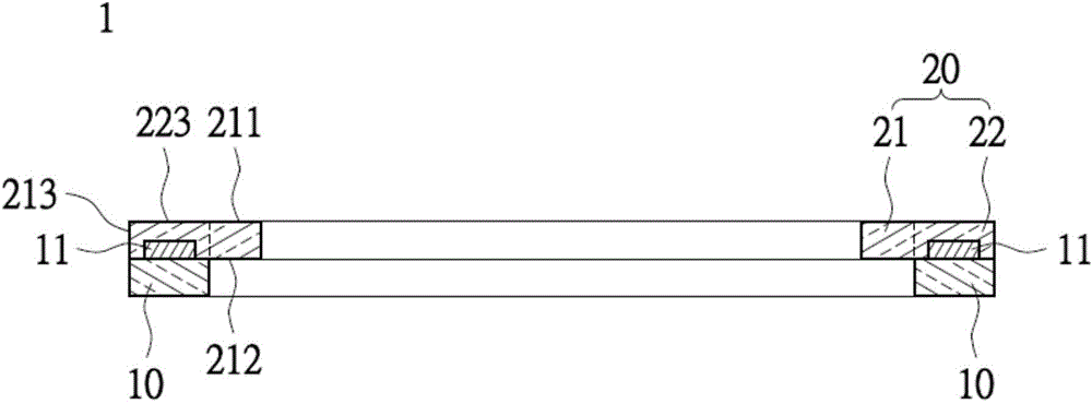
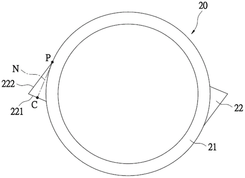
[0050] Please also refer to Figure 1 to Figure 4 , which is a schematic diagram of a side-incidence ring light-emitting device of the present invention. like figure 1 and figure 2 As shown, the annular light emitting device 1 includes: an annular substrate 10 and a light guide ring 20 . At least two light-emitting units 11 are provided on the ring-shaped substrate 10; end position. Wherein, the light-emitting unit 11 may have at least one light-emitting diode, and the form, appearance and color of the light beam emitted by the light-emitting diode can be selected according to practical applications, and no limitation is imposed here.

[0051] Specifically, the number of light emitting units 11 is designed in consideration of the light intensity required to form a sufficient and uniform light emitting surface of the light guide ring 20 . For example, if the side-illuminated ring-shaped lighting device of this embodiment is applied to a large home appliance, such as the o...

Embodiment 2

[0065] Please also refer to Figure 5 to Figure 8 , which is a schematic diagram of the second embodiment of the side-lighting annular light emitting device of the present invention. like Figure 5 , 6As shown, the side-illuminated annular light emitting device 2 includes an annular substrate 10 , a light guide ring 20 and a light-transmitting cover 30 . The detailed descriptions about the annular substrate 10 and the light guide ring 20 are the same as those of the above-mentioned embodiments, and will not be repeated here. The difference between this embodiment and the above-mentioned embodiments is that the annular light-emitting device 1 can further include a light-transmitting cover 30 arranged on the light guide ring 20, which has an upper surface 301 and an inner surface (light guide ring) from the upper surface 301. The direction of the central axis of 20) extends downward to form an inclined surface 302. Wherein, the degree of inclination of the inclined surface 3...


PUM


Abstract

The invention discloses a side-direction inlet light type annular light-emitting device which comprises an annular substrate and a light guide ring. The annular substrate is provided with at least two light-emitting units. The light guide ring is arranged on the annular substrate and provided with an intact annular body and at least two inlet light protruded blocks correspondingly arranged on the side of the annular body. Each inlet light protruded block is provided with inlet light surfaces facing the corresponding light-emitting units and an extension surface connected between the inlet light surfaces and the annular body. The side-direction inlet light type annular light-emitting device is adopted to achieve the effect of a uniform annular light source without a bright (dark) band, and the problem that light leakage and glare easily occur at the inlet light position of the annular light source in the prior art can be effectively solved through the guiding of the inlet light protruded blocks.

Description

technical field [0001] The invention relates to a ring-shaped light emitting device, in particular to a side-incidence type ring-shaped light emitting device. Background technique [0002] Nowadays, ring light sources are widely used, such as rear lights of automobiles, dashboards of automobiles, or backlight modules of operation panels of various electronic products. Generally speaking, most of the common ring light sources nowadays are composed of a plurality of light-emitting diodes and a light guide ring, and these light-emitting diodes are correspondingly arranged below the light guide ring to directly guide light beams into the light guide ring, so that the light guide ring Shines to form a ring light. However, in practical application of this kind of ring light source, there are many deficiencies, for example, the user can easily directly see the bright spots or bright lines produced by the LEDs, and the areas between the LEDs are prone to produce dark areas, while ...

Claims


Application Information

Patent Timeline
Patent Type & Authority Applications(China)
IPC IPC(8): F21S2/00F21V8/00F21Y101/02
Inventor 江丰丞吴健君
Owner 苏州茂立光电科技有限公司
Why Eureka
Try Eureka