
Rotating handle type double-head integrated inflating valve connector

A double-head, rotary handle technology, applied in the direction of valves used for inflation, variable capacity pump components, liquid variable capacity machines, etc., can solve problems such as difficult to master, user-prone to make mistakes, difficult to operate, etc., to eliminate serious Effects of damage, uniform and easy application of force, and avoidance of difficult operation

Inactive Publication Date: 2014-08-27
HENAN UNIV OF SCI & TECH
View PDF6 Cites 0 Cited by
  • Summary
  • Abstract
  • Description
  • Claims
  • Application Information

AI Technical Summary

Problems solved by technology

However, the handle type requires one hand to firmly fix the direction of the joint pipe body to the valve body, and the other hand to move the handle to a 90-degree direction. The force of the two needs to be precisely matched, otherwise the valve will be difficult. Repaired damage, which is difficult for children, the elderly, etc.
Moreover, for the streets carrying multiple joints integrated, due to the simultaneous extrusion of multiple elastic deformation rings in the pipe bodies of multiple joints, greater resistance will be encountered, so it is more difficult to grasp the force of the two.
For some integrated products, when choosing to use different connectors, it is necessary to move the handle to different directions, which makes it easy for users to make mistakes

Method used


Image

  • Rotating handle type double-head integrated inflating valve connector
  • Rotating handle type double-head integrated inflating valve connector
  • Rotating handle type double-head integrated inflating valve connector

Examples


Embodiment Construction

[0021] The embodiments of the present invention will be described in detail below in conjunction with the accompanying drawings. This embodiment is based on the technical solution of the present invention, and provides detailed implementation methods and specific operating procedures, but the scope of protection of the present invention is not limited to the following embodiments. .

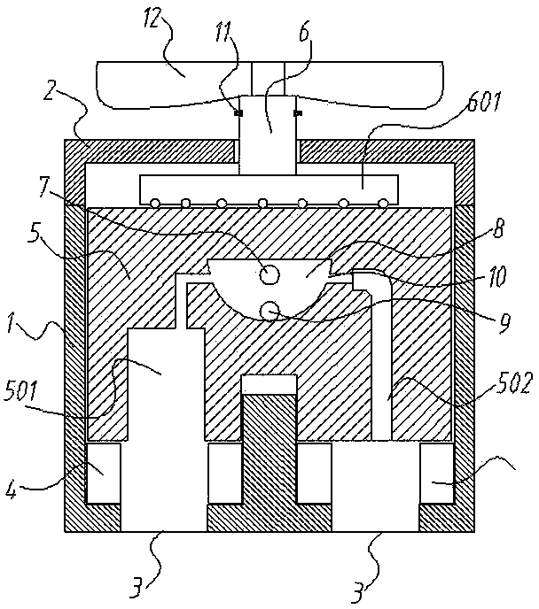
[0022] As shown in the figure, a rotary handle type double-head integrated gas nozzle joint includes a joint body 1 and an upper cover 2 connected to the upper end of the joint body. At the bottom of the joint body 1, there are two The bottom hole 3 of the joint pipe body matched with the upper valve body corresponds to the bottom hole 3 of each joint pipe body. A hollow cylindrical elastic ring 4 is provided in the joint pipe body 1. After installation, the height of the two elastic rings is guaranteed Equal, the upper part of the elastic ring 4 is also provided with a double-link movable body 5...


PUM


Abstract

The invention provides a rotating handle type double-head integrated inflating valve connector. The rotating handle type double-head integrated inflating valve connector comprises a connector pipe body and an upper cover; a hollow cylindrical elastic ring is arranged in the connector pipe body, corresponding to each connector pipe body bottom hole; a double-linkage moving body and an adjusting bolt are arranged at the upper parts of the elastic rings in the connector pipe body; the diameter of an inner hole of each of the elastic rings is more than the outside diameter of a corresponding inflating valve body; air inlet holes for containing air outlet pipes of an inflating device are formed in the outer wall of the connector pipe body and the double-linkage moving body; a central concave hole I and a central concave hole II are formed in the lower end surface of the double-linkage moving body; an air distributing mechanism for adjusting the air feeding direction of the inflating device are arranged between the air inlet holes, the central concave hole I and the central concave hole II. According to the rotating handle type double-head integrated inflating valve connector, connecting and dismounting are accomplished by means of a rotating handle, the operation is simple and easy to master and can be performed with a single hand; in addition, slowly removing during dismounting of the connector cannot cause obvious leakage of air for tires.

Description

technical field [0001] The invention relates to a joint of an inflating device, in particular to a rotary handle type double-head integrated air nozzle joint. Background technique [0002] In my country, there are mainly three types of valves that are widely used: British valves are mainly used in ordinary bicycles and tricycles, and French valves are mainly used in road bicycles and racing cars. One pumping line carries two or even several gas nozzle connectors suitable for various standards, which brings great convenience to the user or operator, and avoids the inconvenience caused by the incorrect model of the gas nozzle connector when inflating. At present, the handle-type double-ended discrete integrated gas nozzle joint has been widely used, and the convenience it brings is very popular. However, the handle type requires one hand to firmly fix the direction of the joint pipe body to the valve body, and the other hand to move the handle to a 90-degree direction. The fo...

Claims


Application Information

Patent Timeline
Patent Type & Authority Applications(China)
IPC IPC(8): F04B39/12F04B33/00F16K24/06
Inventor 王桂泉
Owner HENAN UNIV OF SCI & TECH
Learn More