
heavy duty gearbox

A gearbox and oil supply device technology, which is applied to transmission parts, grain handling, belts/chains/gears, etc., can solve the problems of expensive, sensitive high-pressure pipelines, etc., and achieve the effect of installation space advantage

Inactive Publication Date: 2016-09-21
RENK AG
View PDF8 Cites 1 Cited by
  • Summary
  • Abstract
  • Description
  • Claims
  • Application Information

AI Technical Summary

Problems solved by technology

However, especially high pressure lines are sensitive, elaborate and expensive

Method used


Image

  • heavy duty gearbox
  • heavy duty gearbox
  • heavy duty gearbox

Examples


Embodiment Construction

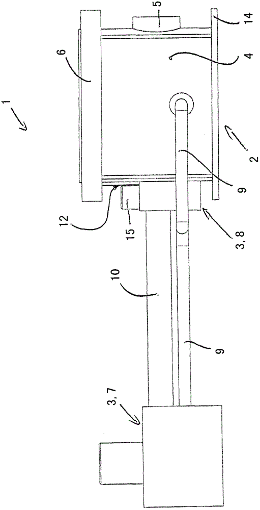
[0030] The invention relates to a heavy-duty gearbox with a gear unit and an oil supply device. The heavy-duty gearbox according to the invention is used in particular in cement mills or coal mills. In the following, refer to Figure 1 to Figure 4 The invention is described for this preferred application of a heavy duty gearbox.

[0031] However, the invention is not limited to this application and the heavy duty gearbox can actually be used in other applications as well.

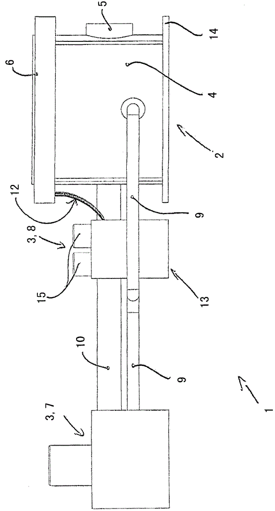
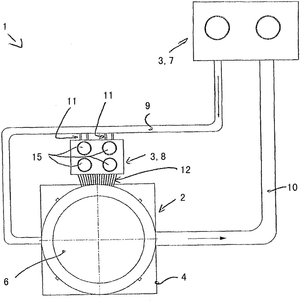
[0032] figure 1 and 2 A heavy-duty gearbox 1 for use in a cement or coal mill is shown, wherein the heavy-duty gearbox 1 comprises a gear unit 2 and an oil supply 3 .

[0033] The gear unit 2 comprises a stator-side housing 4, a rotor-side input shaft 5 which can be driven by a drive motor not shown and figure 1 The invisible output shaft in the figure 1 In the exemplary embodiment, the output shaft drive is used for figure 1 The connecting flange 6 of the unit to be driven is not shown. The unit to...


PUM


Abstract

The heavy duty gearbox (1) has a gearbox unit (2) with a stator-sided housing (4), a rotor-sided input shaft (5) and a rotor-sided output shaft, over which a driven unit is drivable, where the input shaft is driven by a drive motor. A low-pressure part (7) and a high-pressure part (8) of an oil supply unit (3) are separated from one another in a spatial manner, such that the high-pressure part is arranged in immediate vicinity to the gearbox unit, and the low-pressure part is arranged with the distance to the gearbox unit. An independent claim is included for a mill with a grinding head.

Description

technical field [0001] The invention relates to a heavy-duty gearbox according to the preamble of claim 1 . Background technique [0002] Heavy-duty gearboxes, also known as industrial gearboxes, are used in a wide variety of applications, for example as steel production plants and steel processing plants, for cement and coal mills, in the rubber industry and plastics industry Medium, individually produced special gearboxes for transport systems and conveyor systems as well as for power stations. Heavy-duty gearboxes usually transmit a torque of at least 10 kNm, especially at least 50 kNm. A heavy-duty gearbox known from practice comprises a gear unit and an oil supply. The gear unit of the heavy-duty gearbox comprises a stator-side housing, a rotor-side input shaft, which can be driven by a drive motor, and a rotor-side output shaft, wherein the unit to be driven can be driven via the rotor-side output shaft. In the case of cement mills or coal mills, the drivable unit i...

Claims


Application Information

Patent Timeline
Patent Type & Authority Patents(China)
IPC IPC(8): F16H57/04
CPCB02C15/006B02C17/24F16H57/0412F16H57/045F16H57/0471F16H57/0434
Inventor K·邦格S·布伦纳A·巴托斯J·林德C·孙德曼T·施密德鲍尔
Owner RENK AG
Learn More