Self-propelled working robot

a self-propelled, robot technology, applied in the direction of process and machine control, instruments, carpet cleaners, etc., can solve the problems of user inability to easily replace the working part with a different type of working part, use, and relatively heavy weigh

Inactive Publication Date: 2005-09-22
FIGLA
View PDF3 Cites 169 Cited by
  • Summary
  • Abstract
  • Description
  • Claims
  • Application Information

AI Technical Summary

Benefits of technology

[0028] According to this preferred aspect, for example, in the case where the first operation performed by the first working assembly is to apply liquid such as wax onto the floor face and the second operation performed by the second working operation is to clean the floor by sucking dusts on

Problems solved by technology

However, the working robot is mechanically configured so that the user cannot replace easily the working parts with each other and therefore this requires disassembly or assembly by use of tools such as a driver.
Further, since a control part does not have any means for identifying the type of the working part and a separate program is stored in the control part of

Method used


Image

  • Self-propelled working robot
  • Self-propelled working robot
  • Self-propelled working robot

Examples


first embodiment

[0051] Referring to appended figures, a first embodiment of the present invention will be described below.

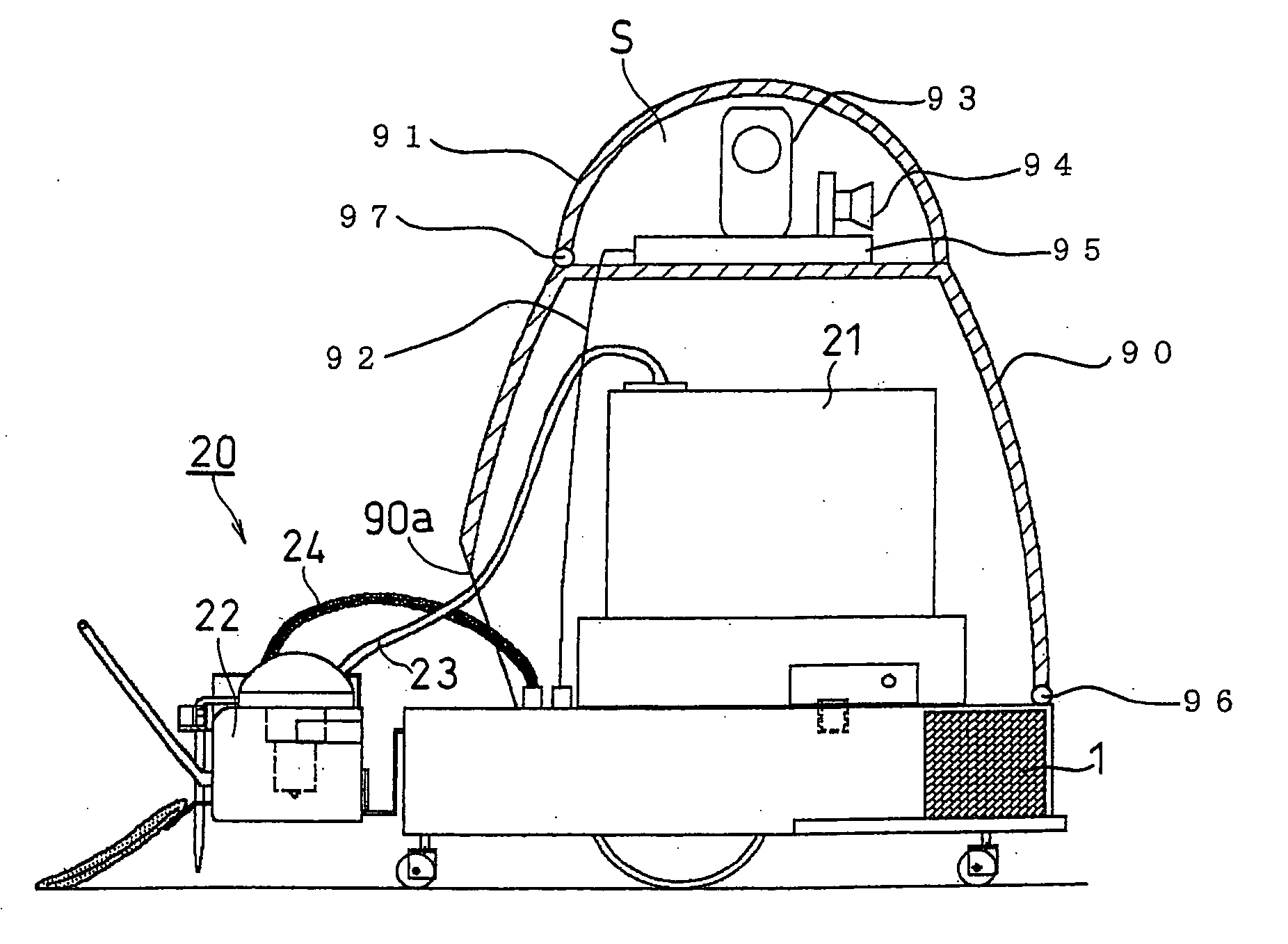
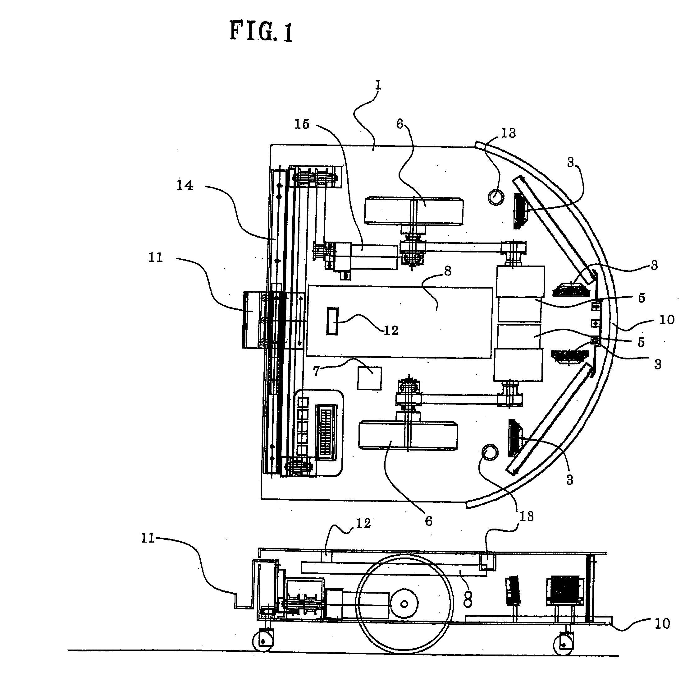
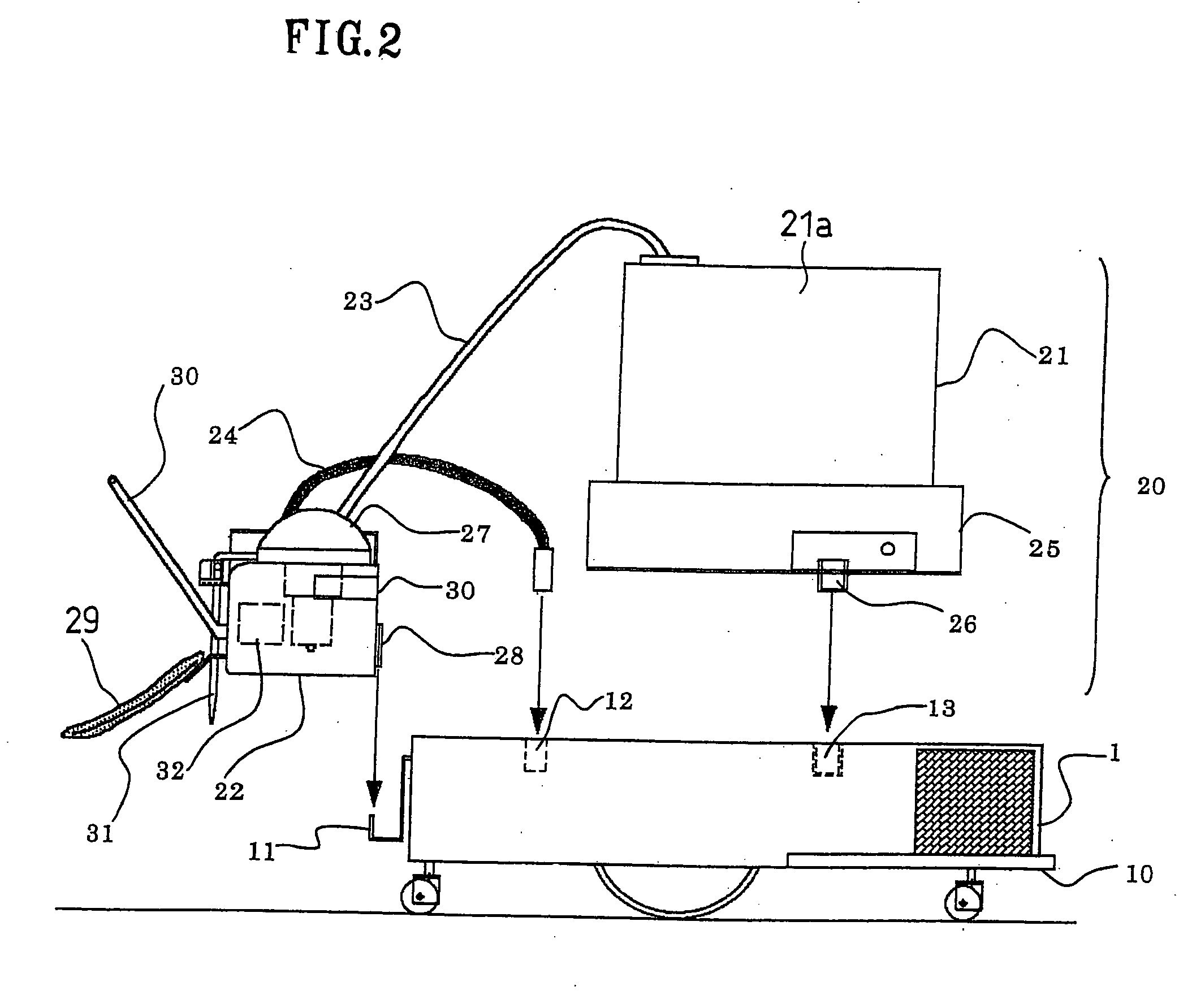
[0052] A working robot of this embodiment has a traveling assembly 1 shown in FIG. 1 as a common configuration and is used after selectively mounting one of various working assemblies on the traveling assembly 1. This first embodiment is described by taking an example where a liquid applying assembly 20 is mounted as a first working assembly.

[0053] As shown in FIG. 1, a working robot according to the present invention has the traveling assembly 1 shaped like a carriage that travels automatically on the floor. A pair of wheels 6 are provided, each on the right and left sides of the traveling assembly 1. The wheels 6 are driven by driving motors 5. The rotational speed of the driving motors 5 is controlled by a control part 8.

[0054] As shown in FIG. 2, the liquid applying assembly 20 has a top unit 21 and a side unit 22. Each of the units 21 and 22 is configured so that they ca...

second embodiment

[0090]FIG. 6 and FIG. 7 show the state where a sucking and cleaning assembly 50, as the second working assembly, is applied on the traveling assembly 1, in place of the liquid applying assembly (the first work assembly) 20. FIG. 8 is a plan view from above, showing the state the sucking and cleaning assembly 50 is mounted on the traveling assembly 1.

[0091] Second Working Assembly:

[0092] The sucking and cleaning assembly 50 is a work assembly which sucks dusts on a flat hard floor or a carpeted floor to clean the floor (an example of the second work). The sucking and cleaning assembly 50 has a top unit 50 and a side unit 51. The top unit 50 is a part relatively heavy in weight, including such elements as a dust storage part (a tank) 52, a blower motor 54, a filter 53, a battery 55 and a first control board 56, which need not be placed near the floor. The side unit 59 has a suction port 59a which is located near the floor and which sucks dusts on the floor.

[0093] The method of atta...


PUM


Abstract

A self-propelled working robot according to the present invention comprises a traveling assembly (1) having a wheel (6) and first and second working assemblies (20, 50) that are detachable from the traveling assembly 81). One of the first and second working assemblies (20, 50) is selectively mounted on the traveling assembly (1). Each working assembly has a type identification means (33) that enables identification of a type of the working assembly. The traveling assembly (1) has a driving motor (5) that drives the wheel (6), a wheel controlling means (41) that controls rotation of the driving motor (5), a discriminating means (38) that discriminates which of the working assemblies is mounted and a work signal output means (39) that outputs a work signal for actuating the working assembly (20, 50) in response to a result of a discrimination.

Description

CROSS-REFERENCE TO RELATED APPLICATIONS [0001] This application is a continuation in part of the PCT international application No. PCT / JP2003 / 013392 filed on Oct. 20, 2003, which claims the priorities on Japanese patent application number 2002-364428, filed in Japan on Nov. 13, 2002, and Japanese patent application number 2003-298193, filed in Japan on Aug. 22, 2003, and this application claims the priority of Japanese patent application number 2004-137997, filed in Japan on May 7, 2004. The entire contents of all these applications are hereby incorporated herein by reference.BACKGROUND OF THE INVENTION [0002] 1. Field of the Invention [0003] The present invention relates to a self-propelled working robot, in particular, a self-propelled working robot capable of performing plural types of operations with respect to a floor. [0004] 2. Background Art [0005] Conventionally, self-propelled working robots have been known in, for example, the following document. [0006] The first non-paten...

Claims


Application Information

Patent Timeline
IPC IPC(8): A47L11/20A47L11/40G06F19/00
CPCA47L11/20A47L11/4061G05D2201/0203G05D1/0219G05D1/0255A47L2201/00
Inventor KAWAGOE, NOBUKAZU
Owner FIGLA
Why Eureka
Try Eureka