Supercharge Your Innovation With Domain-Expert AI Agents!

System and methods for balancing mirrors in limited rotation motor systems

A technology of rotating motors and mirrors, applied in instruments, installations, optics, etc., can solve the problems of increased weight of screw groups, difficulty in perfect balance, and increased inertia

Active Publication Date: 2014-09-03
诺万达公司
View PDF10 Cites 2 Cited by
  • Summary
  • Abstract
  • Description
  • Claims
  • Application Information

AI Technical Summary

Problems solved by technology

The disclosed set of screws is accommodated in the outer rear and two lateral sides of the mirror, but is difficult to use to achieve perfect balance when the mirror itself is very close to balancing
In addition, the use of the screw set disclosed in US Patent 6,972,885 is difficult to achieve front-to-back balance, and the screw set adds weight (increases inertia) and moves when the mirror is moved

Method used


Image

  • System and methods for balancing mirrors in limited rotation motor systems
  • System and methods for balancing mirrors in limited rotation motor systems
  • System and methods for balancing mirrors in limited rotation motor systems

Examples


Embodiment Construction

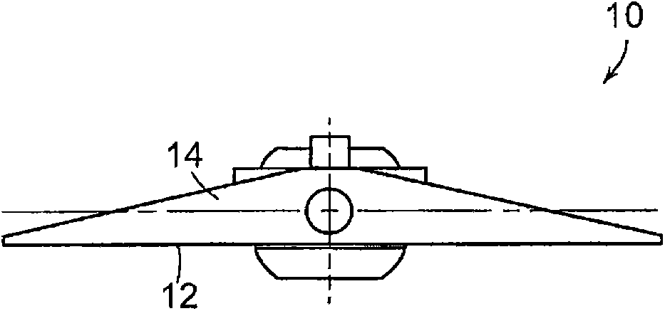
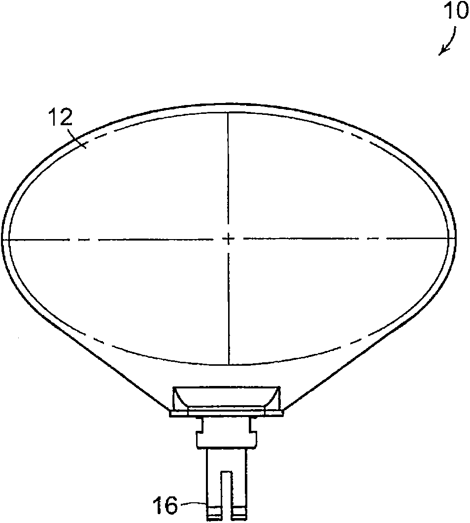
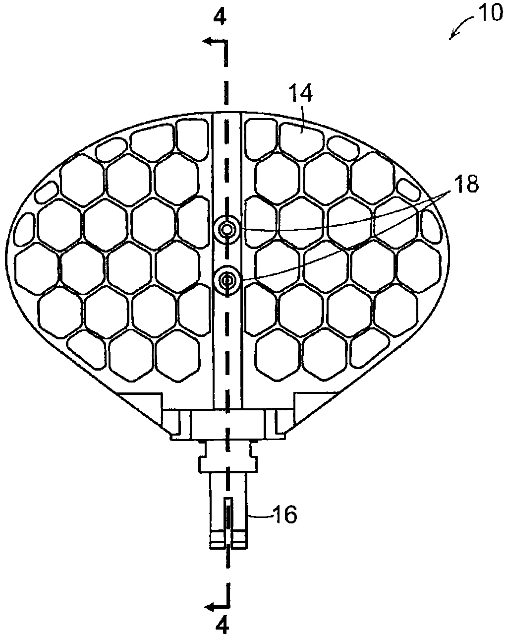
[0033] According to an embodiment, the invention firstly relates to a mirror for a limited rotation motor system, which is slightly obliquely offset in the direction of the front surface of the mirror. For front-to-back balance, one or more threaded weight screws are provided on the back of the mirror. When the weight screws are screwed all the way into the mirror (toward the front surface), the mirror remains biased towards the front, but when one or more weight screws are turned out of the mirror, a front-to-back balance point is obtained.

[0034] Side-to-side balancing is achieved using a pair of opposing weight screws with a tungsten ball locked between them. The tungsten sphere is initially positioned along the centerline of mirror rotation to minimize added inertia. After adjusting the weight screws to their respective points of balance, epoxy was applied to each screw to hold each screw in position so that each weight screw would keep still.

[0035] E.g, Figure 1...


PUM


Abstract

A method of balancing a mirror in a limited rotation motor system is disclosed. The method includes the steps of providing a mirror on a rotor shaft of the limited rotation motor system such that the mirror is initially unbalanced in that the mirror is slightly more weighted to lean to a front side of the mirror that includes a front reflective face of the mirror, and adjusting at least one threaded counterweight screw on a back side of the mirror at least to a position at which the mirror becomes balanced between the front and back sides.

Description

[0001] priority [0002] This application claims U.S. Patent Application Serial No. 13 / 253,194 filed October 5, 2011 and U.S. Provisional Patent Application Serial No. 61 / 513,248 filed July 29, 2011 The entire contents of these patent applications are hereby incorporated by reference as priority claims. Background technique [0003] The present invention relates generally to vibration reduction systems in scanning mirror systems, and in particular to systems for reducing vibration and imbalance in scanning mirror systems including limited rotation motors for scanning a laser beam over a limited angular range. [0004] Scanning mirror systems include continuous rotation motor systems and limited rotation motor systems. A continuous rotation motor system may, for example, include a continuously rotating rotating polygon mirror, and a constrained rotation motor system rotates the rotor back and forth over a limited range of rotation angles. [0005] The balancing system in pri...

Claims


Application Information

Patent Timeline
IPC IPC(8): G02B26/08
CPCG02B26/105G02B7/1821Y10T29/49826
Inventor D·C·布朗
Owner 诺万达公司
Features
  • R&D
  • Intellectual Property
  • Life Sciences
  • Materials
  • Tech Scout
  • Unparalleled Data Quality
  • Higher Quality Content
  • 60% Fewer Hallucinations
Learn More