
Double stroke mechanical latch mechanism

A mechanical and link mechanism technology, applied in the field of circuit switches and latch systems, can solve problems such as increasing reliability and cost

Active Publication Date: 2016-08-17
HUBBELL INC
View PDF4 Cites 0 Cited by
  • Summary
  • Abstract
  • Description
  • Claims
  • Application Information

AI Technical Summary

Problems solved by technology

These requirements increase reliability issues and cost

Method used


Image

  • Double stroke mechanical latch mechanism
  • Double stroke mechanical latch mechanism
  • Double stroke mechanical latch mechanism

Examples


Embodiment Construction

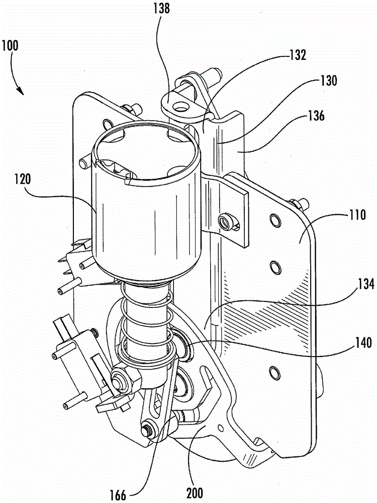
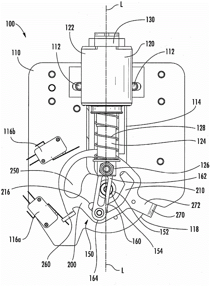
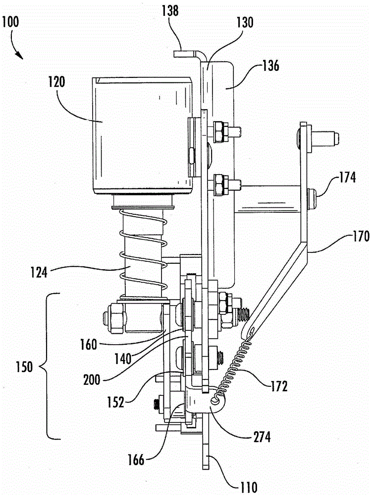
[0017] Referring generally to the figures, a latch mechanism and components thereof are shown in accordance with exemplary embodiments. A latch mechanism typically includes a solenoid, an operating lever, and a mechanical linkage (shown including a cam) coupling the solenoid to the operating lever. Actuation of the mechanical linkage causes the operating rod to move between the retracted position and the extended position. Additionally, the linkage mechanism provides a crank action. That is, each time the solenoid is actuated, it provides opposite linear motion on the operating rod. Thus, a unidirectional solenoid can be used to provide both push and pull functionality, thereby reducing cost and complexity, which in turn increases reliability.

[0018] According to an exemplary embodiment, a latch system may be used as a vacuum interrupter based medium voltage capacitor switch. In this embodiment, the lever may be configured to selectively couple at least two electrical con...


PUM


Abstract

The invention provides a switch for an electric circuit. The switch includes: a base; a cam rotatably coupled to the base and defining a first profile and a second profile; a solenoid having alternating first and second cycles; a link including a first a portion and a second portion; and a member configured to move between an extended position and a retracted position and including a cam follower configured to follow the second profile. The first profile of the cam includes a first position, a second position, a third position and a fourth position. The first cycle of the solenoid includes a first energized state and a first de-energized state and the second cycle of the solenoid includes a second energized state and a second de-energized state.

Description

Background technique [0001] The present invention relates generally to the field of latch mechanisms. More particularly, the present invention relates to the field of solenoid-actuated electromechanical switches. [0002] In the field of capacitor switches (eg, vacuum interrupter based voltage switches), operating levers are used to separate and connect electrical contacts together. Conventional switches use magnetic actuators to move levers to separate and connect electrical contacts together. Magnetic actuators use rare earth magnets to hold the operating rod at the end of each stroke, are expensive and require precise control. Other conventional switches use a motor-operated, spring-loaded mechanism to move a lever to separate and connect electrical contacts together. Motor operated spring loaded mechanisms are complex, expensive and have limited speed. Other switches have used solenoid-actuated mechanisms to move the operating rod, requiring one solenoid for each direc...

Claims


Application Information

Patent Timeline
Patent Type & Authority Patents(China)
IPC IPC(8): H01H50/54
CPCH01H3/56H01H3/42H01F7/124H01H50/44H01H50/644
Inventor 约瑟夫·P·格罗瓦茨
Owner HUBBELL INC
Learn More