Active clamping circuit driven by IGBT

A technology of clamping circuit and driving circuit, which is applied in the direction of circuit devices, emergency protection circuit devices, emergency protection circuit devices for limiting overcurrent/overvoltage, etc., and can solve the problem of limited driving capability of integrated driver chips and independent integrated driver chips. Electromagnetic interference, failure to meet the flexible adjustment of drive capacity and line protection capacity, etc., to avoid the effect of overvoltage

Inactive Publication Date: 2014-09-17
BEIJING CED RAILWAY ELECTRIC TECH
View PDF5 Cites 17 Cited by
  • Summary
  • Abstract
  • Description
  • Claims
  • Application Information

AI Technical Summary

Problems solved by technology

[0006] In the prior art, the widely used IGBT drive circuit is an independent integrated drive chip that can be obtained through commercial means, such as CONCEPT Company; this integrated drive chip not only has limited drive capability, but also it is difficult to flexibly adjust the parameters in the circuit. Therefore, this independent integrated drive chip cannot meet the needs of electric locomotives to flexibly adjust the drive capability and line protection capabilities of IGBT drive circuits in different application scenarios; on the other hand, due to the harsh electromagnetic environment on electric locomotives, independent integration Drive chips are prone to failure due to electromagnetic interference. Therefore, in the prior art, independent integrated drive chips often cannot guarantee the safe and reliable operation of IGBT converters in the complex environment of electric locomotives. Specially designed drive circuits are basically used.

Method used


Image

  • Active clamping circuit driven by IGBT
  • Active clamping circuit driven by IGBT
  • Active clamping circuit driven by IGBT

Examples


Embodiment 1

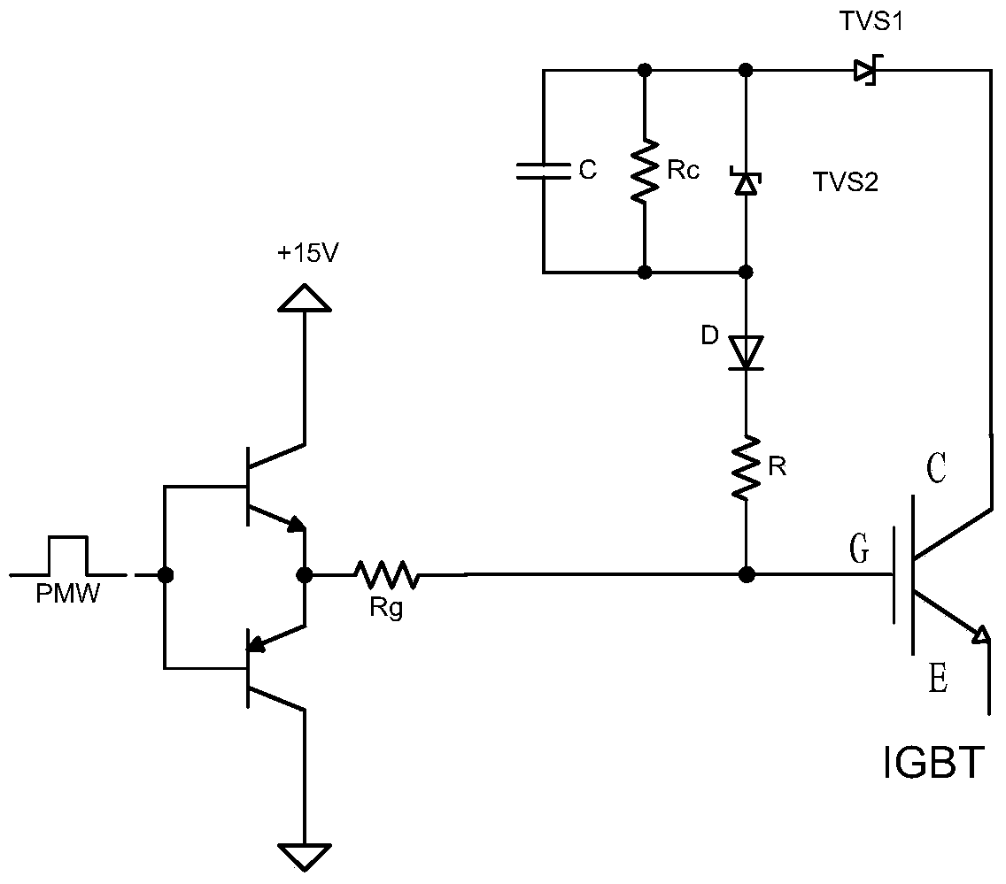
[0031] Such as Figure 4 As shown, an IGBT driving active clamping circuit is a part of the IGBT driving circuit, which is connected between the collector and the gate of the IGBT of the converter, and its specific structure can adopt the above technical solutions. The active clamping circuit has been successfully applied to the design of the IGBT drive circuit of the locomotive traction converter. In the 1800VDC-1300VAC two-level three-phase inverter, it is used to actively clamp the 3300V, 1200A IGBT Bit protection.

Embodiment approach

[0033] (1) in Figure 4 In the circuit shown, D1 to D30 are VISHAY's SMCJ series transient voltage suppression diodes, among which D1 to D22 are SMCJ100A, and D23 to D25 are SMCJ5A. They form a series combination of TVS1, U TVS1 The voltage threshold is 2215V; D26 to D29 are SMCJ150A, they form a series combination of TVS2, U TVS2 The voltage value is 600V, U TVS The voltage threshold is 2815V; D30 is SMCJ33A, which acts as a diode D to prevent the IGBT gate voltage from flowing to the collector.

[0034] (2) in Figure 4 In the circuit shown, C1 is a 22nF, 1000V metallized polypropylene film capacitor. The resistors R1 to R4 are 221k ohm metallized film resistors, and they are combined in series to form a discharge resistor Rc. The resistors R5 to R7 are metalized film resistors of 22 ohms, and they are combined in parallel to form a current limiting resistor R.

[0035] It can be seen that the embodiment of the present invention can perform device selection and parameter desig...


PUM


Abstract

The invention discloses an active clamping circuit driven by an IGBT. The active clamping circuit comprises a first transient voltage restraint diode, a second transient voltage restraint diode, a diode and a current-limiting resistor, the first transient voltage restraint diode, the second transient voltage restraint diode, the diode and the current-limiting resistor are sequentially connected between a collector and a grid of the IGBT, and a capacitor and a discharging resistor are connected to the second transient voltage restraint diode in parallel. Protection on a dynamic active clamp and a fixed active clamp of the IGBT is achieved. The active clamping circuit is simple in structure and high in universality, parameter setting of active clamping voltage can be carried out according to various application occasions, and the active clamping circuit can be applied to design of IGBT driving circuits under various working conditions.

Description

Technical field [0001] The invention relates to a converter for electric locomotives, in particular to an active clamp circuit driven by IGBT of the converter for electric locomotives. Background technique [0002] IGBT (Insulated Gate Bipolar Transistor, insulated gate bipolar transistor) combines the advantages of a power field effect transistor (MOSFET) and a bipolar power transistor (BJT), which has high input impedance, fast switching speed, and good thermal stability It also has the advantages of low on-state voltage, high withstand voltage and large withstand current. Therefore, it is more and more widely used in modern power electronic technology. [0003] One of the key technologies for IGBT application is overvoltage suppression. Overvoltage suppression is not only directly related to the operating characteristics and operational safety of the IGBT itself, but also affects the performance and safety of the entire system. When the IGBT is normally turned off, a certain v...

Claims


Application Information

Patent Timeline
Patent Type & Authority Applications(China)
IPC IPC(8): H02H9/04
Inventor 刘志华贺觅知赵利忠仝超
Owner BEIJING CED RAILWAY ELECTRIC TECH
Why Eureka
Try Eureka