
a stamping machine

A technology of punching machine and punching mechanism, applied in the field of punching machine, can solve problems such as punching die stuck, achieve the effect of high automation level, reduce labor intensity and simple structure

Active Publication Date: 2016-08-17
ANHUI HONGQIAO METAL MFG
View PDF7 Cites 0 Cited by
  • Summary
  • Abstract
  • Description
  • Claims
  • Application Information

AI Technical Summary

Problems solved by technology

The stamping mechanism rises after stamping, and the telescopic rod pulls the partition to rise, and the partition separates the workpiece from the punch, which solves the problem that the workpiece is easily stuck with the punch after stamping, reduces the labor intensity, and has a simple and practical structure.

Method used


Image

  • a stamping machine

Examples


Embodiment Construction

[0023] The present invention is described further below:

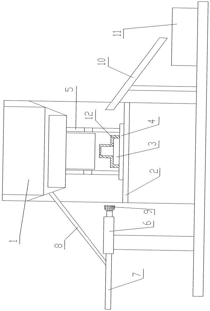
[0024] combine figure 1 : A stamping machine, comprising a stamping mechanism 1, a workbench 2, a punch 3, a partition 4, a telescopic rod 5, a chute 6, a slide bar 7, a connecting rod 8, a trough 10, a storage box 11, and a punch 3 is placed on the surface of the workbench 2, and the separator 4 is set on the outside of the punch 3, so as not to interfere with the normal operation of the stamping mechanism 1. One end of the telescopic rod 5 is connected to the partition 4, and the other end is connected to the stamping mechanism 1. The maximum expansion and contraction of the telescopic rod 5 The length value is not greater than the maximum value of the vertical height from the connection between the telescopic rod 5 and the stamping mechanism 1 to the upper surface of the punch 3; when the stamping mechanism 1 rises to the highest position, the partition 4 should drive the workpiece 12 to leave the punch 3, and The ...


PUM


Abstract

The invention discloses a stamping machine, which comprises a stamping mechanism, a workbench, a punch, a partition, and a telescopic rod. The punch is placed on the surface of the worktable, and the partition is set outside the punch. One end of the telescopic rod is connected to the partition, and the other end is connected to the stamping mechanism. The maximum telescopic length of the telescopic rod is not greater than the connection between the telescopic rod and the stamping mechanism to the upper surface of the punch. The maximum value of the vertical height, the body length of the telescopic rod is not greater than the length from the connection between the telescopic rod and the stamping mechanism to the connection between the telescopic rod and the partition. The invention uses the stamping mechanism to rise and fall to pull the partition to move, thereby driving the workpiece to move; the slide bar impacts the workpiece into the trough; solves the problem that the workpiece is easily stuck with the punch after stamping, reduces the labor intensity and improves the automation level High, simple structure and practical.

Description

technical field [0001] The invention relates to a stamping machine. Background technique [0002] The principle of the stamping machine is to drive the flywheel through the motor, and through the clutch, the transmission gear drives the crank linkage mechanism to move the slider up and down, and drives the drawing die to form the steel plate. The so-called double action means that the press has two sliders, which are divided into an inner slider and an outer slider. The inner slider drives the punch or die of the mold, and the outer slider drives the blankholder on the mold. When the blank holder first moves to press the edge of the steel plate, the inner slider moves again to stretch. [0003] Stamping relies on presses and molds to apply external forces to plates, strips, pipes, and profiles to cause plastic deformation or separation to obtain workpieces (stampings) of required shape and size. [0004] Stamping processing is a production technology that uses the power of...

Claims


Application Information

Patent Timeline
Patent Type & Authority Patents(China)
IPC IPC(8): B21D45/08B21D43/20B21D22/20
Inventor 余昌国李红杰
Owner ANHUI HONGQIAO METAL MFG
Features
  • Generate Ideas
  • Intellectual Property
  • Life Sciences
  • Materials
  • Tech Scout
  • Unparalleled Data Quality
  • Higher Quality Content
  • 60% Fewer Hallucinations
Learn More