
A stamping device for easy demoulding

A stamping device and demoulding technology, which is applied in the field of stamping machinery, can solve problems such as being stuck on the mold and not being resolved, and achieve the effects of simple structure, high automation level, and reduced labor intensity

Active Publication Date: 2016-11-16
ANHUI HONGQIAO METAL MFG
View PDF8 Cites 0 Cited by
  • Summary
  • Abstract
  • Description
  • Claims
  • Application Information

AI Technical Summary

Problems solved by technology

This technical solution does not solve the problem that the workpiece is easily stuck on the mold after stamping, and needs to be improved

Method used


Image

  • A stamping device for easy demoulding
  • A stamping device for easy demoulding
  • A stamping device for easy demoulding

Examples


Embodiment 1

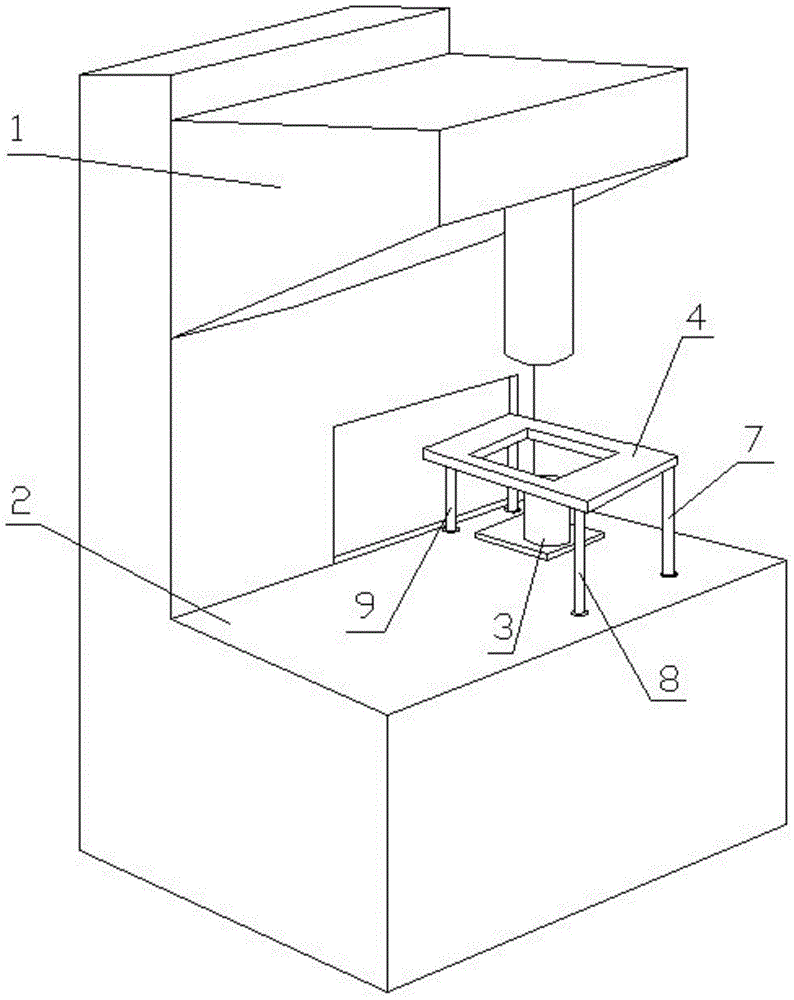
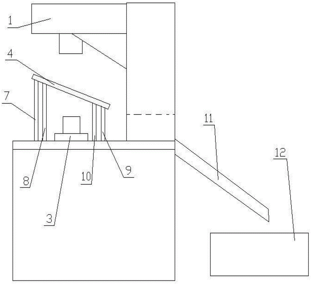
[0028] to combine figure 1 , figure 2 : A stamping device that is convenient for demoulding, including a stamping mechanism 1, a workbench 2, a punch 3, a trough 11, a storage box 12, a partition 4, a driving device, the punch 3 is placed on the surface of the workbench 2, and the partition The plate 4 is set on the outside of the punch 3, and the driving device includes 4 cylinders, namely the third cylinder 7, the fourth cylinder 8, the fifth cylinder 9, and the sixth cylinder 10, which are symmetrical with respect to the punch 3, and are sequentially connected with the partition plate 4. The bottom is connected, the telescopic heights of the third and fourth cylinders are greater than those of the fifth and sixth cylinders, and the driving device is electrically connected with the stamping mechanism 1 .

[0029] After the stamping operation of the impact mechanism 1 is finished, the stamping mechanism 1 rises. At this time, the driving device receives a signal, and the cy...

Embodiment 2

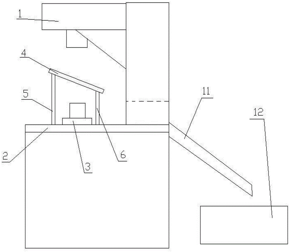
[0035] to combine image 3 : A stamping device that is convenient for demoulding, including a stamping mechanism 1, a workbench 2, a punch 3, a trough 11, a material storage box 12, a partition 4, a driving device, the punch 3 is placed on the surface of the workbench 2, and the partition The plate 4 is set on the outside of the punch 3, and the driving device includes two cylinders, that is, the first cylinder 5 and the second cylinder 6, which are located on both sides of the punch 3. The first and second cylinders are connected to the bottom of the partition 4, and the second cylinder The telescopic height of the first air cylinder 5 is greater than that of the second air cylinder 6 , and the driving device is electrically connected with the stamping mechanism 1 .

[0036] After the stamping operation of the impact mechanism 1 is finished, the stamping mechanism 1 rises. At this time, the driving device receives a signal, and the cylinder drives the partition 4 to rise. The...


PUM


Abstract

The invention discloses a stamping device for easy demoulding, which includes a stamping mechanism, a workbench, and a punch. The punch is placed on the surface of the workbench, and also includes a partition and a driving device. The outer side of the punch, the driving device is connected to the bottom of the partition, and the driving device is electrically connected to the stamping mechanism. The invention drives the separator to rise through the driving device, thereby driving the workpiece to be demolded; the invention solves the problem that the workpiece is easily stuck with the punch after stamping, reduces the labor intensity, has a high level of automation, and is simple and practical in structure.

Description

technical field [0001] The invention relates to the technical field of stamping machinery, in particular to a stamping device for easy demoulding. Background technique [0002] The principle of the stamping machine is to drive the flywheel through the motor, and through the clutch, the transmission gear drives the crank linkage mechanism to move the slider up and down, and drives the drawing die to form the steel plate. The so-called double action means that the press has two sliders, which are divided into an inner slider and an outer slider. The inner slider drives the punch or die of the mold, and the outer slider drives the blankholder on the mold. When the blank holder first moves to press the edge of the steel plate, the inner slider moves again to stretch. [0003] Stamping relies on presses and molds to apply external forces to plates, strips, pipes, and profiles to cause plastic deformation or separation to obtain workpieces (stampings) of required shape and size. ...

Claims


Application Information

Patent Timeline
Patent Type & Authority Patents(China)
IPC IPC(8): B21D45/08B21D22/02
Inventor 余昌国李红杰
Owner ANHUI HONGQIAO METAL MFG
Features
  • Generate Ideas
  • Intellectual Property
  • Life Sciences
  • Materials
  • Tech Scout
  • Unparalleled Data Quality
  • Higher Quality Content
  • 60% Fewer Hallucinations
Learn More