
Power Supply Device For Arc Welding And Control Method Of Power Supply Device For Arc Welding

A technology of arc welding and power supply device, which is applied in the direction of arc welding equipment, welding equipment, manufacturing tools, etc., which can solve the problems of reduced welding performance and hindrance of welding continuity, and achieve good arc welding effect

Active Publication Date: 2014-09-24
DAIHEN CORP
View PDF5 Cites 3 Cited by
  • Summary
  • Abstract
  • Description
  • Claims
  • Application Information

AI Technical Summary

Problems solved by technology

If the feeding speed of the welding wire is not appropriately adjusted in accordance with the change in the distance between the tip base metals as described above, the welding performance may be reduced or the continuity of welding may be hindered depending on the situation.

Method used


Image

  • Power Supply Device For Arc Welding And Control Method Of Power Supply Device For Arc Welding
  • Power Supply Device For Arc Welding And Control Method Of Power Supply Device For Arc Welding
  • Power Supply Device For Arc Welding And Control Method Of Power Supply Device For Arc Welding

Examples


no. 1 Embodiment approach

[0043] Hereinafter, the first embodiment of the power supply device for arc welding and the control method of the power supply device for arc welding will be described.

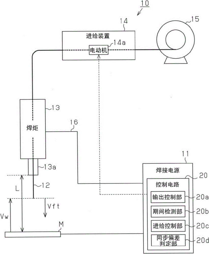
[0044] like figure 1 As shown, as an arc welding machine 10, it is equipped with: a power supply device 11 for arc welding that generates output power suitable for arc welding; a welding torch 13 for supplying and maintaining power supply to a welding wire 12 as a discharge electrode that generates an arc; A feeding device 14 for feeding the welding wire 12 ; and a welding wire holder 15 around which the welding wire 12 is wound.

[0045] The welding torch 13 is connected to a power supply device 11 via a cable 16 and receives power from the power supply device 11 . The welding torch 13 includes a power supply tip 13 a for supplying power to the welding wire 12 . The power supply terminal 13 a allows the feeding operation of the welding wire 12 and makes electrical contact to supply the output power generat...

no. 2 Embodiment approach

[0075] Hereinafter, the second embodiment of the power supply device for arc welding and the control method of the power supply device for arc welding will be described.

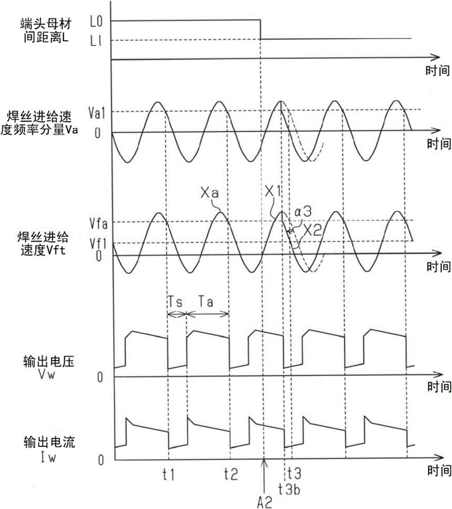
[0076] In this embodiment, the control method of the feed control part 20c of the control circuit 20 is different from the previous 1st Embodiment. In the first embodiment, the phase adjustment (fixed amplitude) of the feed speed Vft of the welding wire 12 on the change curve Xa is performed, but the present embodiment is a control method in which the feed speed Vft of the welding wire 12 is adjusted on the change curve Xa. Amplitude adjustment (phase fixed).

[0077] "When the distance L between the terminal base metals is extended"

[0078] Such as Figure 4 As shown, when the deviation between the actual time t3a and the original time t3 of switching to the short-circuit period Ts exceeds the allowable range, and the actual time t3a is slower than the original time t3, the synchronization deviation dete...


PUM


Abstract

The invention provides a power supply device, which appropriately controls a feed speed of a welding wire to perform arc welding, for the arc welding and a control method of the power supply device for the arc welding. As feed control of the welding wire (12), the feed speed (Vft) of the welding wire (12) is changed periodically, so, when the welding wire (12) is in positive feed and the feed speed (Vft) is in a speed reduction area of a change curve, the feed control is switched to a short-circuit period, and adjustments of the feed speed (Vft) of the welding wire (12) are performed in the speed reduction area. If a judgment of a feed speed synchronization error representing that the feed speed (Vft) of the welding wire (12) is slow is completed, acceleration control comprising temporary acceleration is implemented; and, if a judgment of a feed speed synchronization error representing that the feed speed (Vft) of the welding wire (12) is fast is completed, speed reduction control enabling the feed speed to be further reduced is implemented.

Description

technical field [0001] The present invention relates to a power supply device for consumable electrode type arc welding and a control method for the power supply device for consumable electrode type arc welding. Background technique [0002] In consumable electrode arc welding, an arc is generated from the tip of the electrode using the welding wire as the discharge electrode to weld the workpiece (base metal). However, at this time, the welding wire is consumed by the arc, so the consumption Welding is performed while feeding the welding wire accordingly. In addition, in this consumable electrode type arc welding, a short-circuit period in which the welding wire is in contact with the workpiece and an arc period in which the arc is generated by separating the welding wire from the workpiece alternately occur. Advancement (forward feed) and retreat (reverse feed) of the welding wire are repeated in each period (for example, refer to Patent Document 1). [0003] Patent Docu...

Claims


Application Information

Patent Timeline
IPC IPC(8): B23K9/10B23K9/095
CPCB23K9/095B23K9/1006B23K9/073B23K9/09B23K9/0956B23K9/124
Inventor 田中利幸
Owner DAIHEN CORP
Features
  • Generate Ideas
  • Intellectual Property
  • Life Sciences
  • Materials
  • Tech Scout
  • Unparalleled Data Quality
  • Higher Quality Content
  • 60% Fewer Hallucinations
Learn More