Power Supply Device For Electrical Arc Welding And Controlling Method Therefor

A technology of arc welding and power supply device, which is applied in the direction of arc welding equipment, welding equipment, manufacturing tools, etc. It can solve the problems of welding performance degradation and hinder welding continuation, and achieve good arc welding effect

Active Publication Date: 2014-09-24
DAIHEN CORP
View PDF8 Cites 4 Cited by
  • Summary
  • Abstract
  • Description
  • Claims
  • Application Information

AI Technical Summary

Problems solved by technology

If the feeding speed of the wire is not properly adjusted according to the change in the distance between the chip base metals, there is a risk that the welding performance will be reduced or the continuation of welding may be hindered depending on the situation.

Method used


Image

  • Power Supply Device For Electrical Arc Welding And Controlling Method Therefor
  • Power Supply Device For Electrical Arc Welding And Controlling Method Therefor
  • Power Supply Device For Electrical Arc Welding And Controlling Method Therefor

Examples


no. 1 Embodiment approach

[0044] Hereinafter, the first embodiment of the power supply device for arc welding and the control method of the power supply device for arc welding will be described.

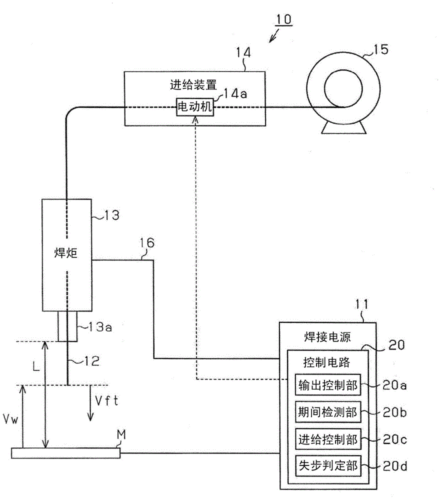
[0045] Such as figure 1As shown, the arc welding machine 10 includes not only an arc welding power supply device 11 that generates an output power suitable for arc welding, but also a device for feeding and holding the welding wire 12 as a discharge electrode that generates an arc. A welding torch 13 , a feeding device 14 for feeding the welding wire 12 , and a wire reel 15 on which the welding wire 12 is wound.

[0046] The welding torch 13 is connected to a power supply device 11 via a power cable 16 and receives power supply from the power supply device 11 . The welding torch 13 is equipped with the feeding chip (chip) 13a which feeds the welding wire 12. As shown in FIG. The power feeding chip 13 a is in electrical contact with the welding wire 12 in order to supply the output power generated by the pow...

no. 2 Embodiment approach

[0076] Hereinafter, the second embodiment of the power supply device for arc welding and the control method of the power supply device for arc welding will be described.

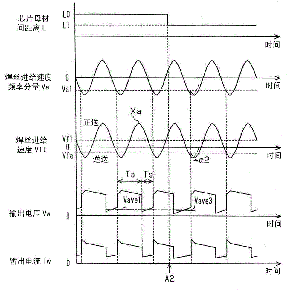
[0077] In this embodiment, the control form of the feed control part 20c of the control circuit 20 differs from the previous 1st Embodiment. In the first embodiment, the phase adjustment (fixed amplitude) of the change curve Xa of the feed speed Vft of the welding wire 12 was performed, whereas in the present embodiment, the change curve of the feed speed Vft of the welding wire 12 is performed. Control form of amplitude adjustment (phase fixation) of Xa.

[0078] "When the distance L between chip base materials is elongated"

[0079] Such as Figure 4 As shown, when the average voltage of the output voltage Vw during the short-circuit period Ts exceeds the allowable range, for example, when it rises from Vave1 to Vave2, the out-of-synchronization determination unit 20d determines that the distance L betwe...


PUM


Abstract

The invention provides a power supply device for electrical arc welding and a controlling method therefor. Great electrical welding can be achieved when feedingspeed of welding wires can be properly controlled. Feeding speed (Vft) of a welding wire (12) can be controlled to periodically change, so the welding wire (12) in switch between positive and negative feeding can be switched to an electric arc period and during negative feeding of the welding wire, the feeding speed (Vft) of the welding wire (12) can be adjusted; when the feeding speed (Vft) of the welding wire (12) is determined to be slower than certain speed, acceleration control in the negatie feeding direction can be applied; and when the speed (Vft) of the welding wire (12) is determined to be quicker than the certain speed, deceleration control in the negatie feeding direction can be applied.

Description

technical field [0001] The present invention relates to a consumable electrode type arc welding power supply device and a control method of the consumable electrode type arc welding power supply device. Background technique [0002] In arc welding of the consumable electrode type, the welding object (base metal) is welded by using a welding wire as a discharge electrode and generating an arc from the tip of the electrode. However, at this time, the welding wire is consumed by the arc, so corresponding to this consumption, Welding is performed while feeding the welding wire. In this consumable electrode type arc welding, the short-circuit period in which the wire contacts the workpiece and the arc period in which the wire separates from the workpiece to generate an arc alternately occur. , repeatedly advancing (forward feeding) and retreating (reverse feeding) of the welding wire (for example, refer to Patent Document 1). [0003] Prior art literature [0004] patent docum...

Claims


Application Information

Patent Timeline
Patent Type & Authority Applications(China)
IPC IPC(8): B23K9/10B23K9/095
CPCB23K9/073B23K9/095B23K9/125B23K9/09B23K9/0956B23K9/1006B23K9/124
Inventor 田中利幸
Owner DAIHEN CORP
Why Eureka
Try Eureka