Brush-sieve powder fluidizing apparatus for nano-size and ultra fine powders

a technology of fluidizing apparatus and powder, which is applied in the direction of packaging, packaging goods type, coatings, etc., can solve the problems of ultra-fine powders, nano-size materials, agglomeration of larger particles within the fluidized stream, and not concerned with maintaining a consistent flow over a wide distribution of particle sizes, etc., to achieve the effect of simplifying the manufacturing of the powder-fluidizing apparatus

Active Publication Date: 2020-07-28
INNOVATION TECH INC
View PDF23 Cites 1 Cited by
  • Summary
  • Abstract
  • Description
  • Claims
  • Application Information

AI Technical Summary

Benefits of technology

[0013]In keeping with one aspect of the present invention, a powder-fluidizing apparatus and process is particularly applicable to feeding ultra-fine powders, including nano-size materials, and feeding powders with a broad particle size distribution, typically 0.1 micron to 50 micron in size, in a uniform manner over a long period of time. The powders are fed into applicators such as coating and spray forming nozzles and guns. A powder-fluidizing apparatus and process employs novel techniques for feeding the aforementioned types of powders. The improvement over the prior art disclosed in U.S. Pat. No. 7,273,075 B2 is an advanced embodiment using the pressure vessel operating as both a containment vessel for the pressurized carrier gas and a reservoir for the powder. This approach simplifies the manufacturing of the powder-fluidizing apparatus with fewer parts and allows the pressure vessel to simultaneously serve as the shipping or transportation canister for hermetically sealing and storing powder.
[0014]Moreover, the present powder-fluidizing apparatus and process feeds the aforementioned types of powders by rotating a three-prong brush, in contact with a removable sieve disc packet, and sweeping the powder through holes in the sieve disc in order to break up agglomerated particles in the powder and control the feed rate of the powder to the applicator.
[0015]A further aspect of the invention enables switching the powder feed “off” and “on” without substantially perturbing the gas flow conditions (pressure and gas flow rate) through the pressure vessel. This improvement is made possible by controlling the rotation state (“on / off”) of the motor driving the brush in contact with the sieve. When the motor is switched “on” powder loaded into the pressure vessel is uniformly metered through the sieve by the rotating brush in contact with the sieve. Alternatively, when the motor is switched “off” the sieve mesh size is uniquely selected to retain the powder without permitting powder particles to trickle through the sieve. This enables a uniform metering of powder into the carrier gas stream flowing through the pressure vessel to the applicator when the motor driving the rotatable brush is switched “on”, and preventing the feed of powder when the motor driving the brush is switched “off.”
[0016]Feeding powder into the carrier gas stream without significantly perturbing the gas pressure and flow rates is an aspect of the invention. This feature is helpful for depositing coatings with alternating layers of powder materials during buildup or for switching between a grit blast media held in one powder fluidizing unit and a selected powder held in a second powder fluidizing unit for depositing as a coating. The independency of the powder feed and the gas pressure and flow conditions also enables a method for conserving powder or precluding the deposition of powder when articulating the applicator gun / nozzle to different positions on the part or substrate surface being coated by simply switching “off” the motor driving the brush rotation on the sieve.
[0017]The powder swept through the holes drops into a fluidizing funnel mounted in the base of the powder-fluidizing apparatus, where being entrained into a carrier gas subsequently fluidizes it. The entrained powder and gas then flow through the funnel and into an outlet fitting attached to a conventional hose for conveying the carrier gas and entrained powder to the applicator. The funnel assembly is constructed of lightweight aluminum alloy and is loosely mounted and constrained with bolts to the base of the pressure vessel so that it is able to be repeatedly shock vibrated or pinged with the armature of a solenoid to avoid powder build-up on the inner surface of the funnel assembly that can break loose and cause pulsing of powder in the carrier gas flow. The motion of the solenoid is driven by a square wave pulse at a frequency to maximize the shock impact to the funnel assembly. Installing rubber washers in the armature cavity can reduce the acoustic noise to levels below 75 dBA. Ultrasonic waves can also be introduced into the funnel assembly with an ultrasonic transducer to break up any agglomerated particles remaining in the powder before it reaches the applicator.
[0020]Such methods for feeding and conveying powders to a reactor or nozzle mixing chamber for high-temperature decomposition of organoaluminum precursor compounds or other reactive vapor materials to thin-film coat the powders prior to deposition with an applicator can be used to enhance corrosion resistance and cohesion strength of impact consolidated coatings.

Problems solved by technology

However, these approaches are designed for fluidizing larger particle sizes (e.g., particles larger than 635 mesh or 20 micrometers) and are not concerned with maintaining a consistent flow over a wide distribution of particle sizes within the fluidized stream.
In conventional powder feeders, ultra-fine powders, including nano-size materials, tend to agglomerate into larger size particles that do not feed uniformly through the feeder and frequently plug the feeder's orifices.
Furthermore, conventional powder feeders do not maintain a constant flow over a wide distribution of powder particle sizes.
This works well for soft materials such as baking flour, but metal powders are much more abrasive and will quickly wear out either the sieve or the scraper.
This action tends to cause non-uniformity in the powder feed rate.
The limitation of U.S. Pat. No. 9,505,566 is that the metering of powder through the sieve is dependent on the differential pressure between the powder reservoir and the powder outlet of the device and vibration of the entire mass of powder in the powder reservoir.
These dependencies can result in non-uniform feeding of powder and a condition in which powder continues to feed through the sieve even when the motor driving the brush is turned off.
None of the aforementioned devices and methods focus on brushing dry powder through a sieve disc for the purpose of both breaking up agglomerated powder particles and simultaneously fluidizing these particles into a carrier gas.
More importantly, the prior art of U.S. Pat. No. 7,273,075 does not claim to be able to switch powder feed on or off without substantially perturbing the gas pressure and flow conditions.
However, neither of these patents discloses a method for brushing dry powders through a sieve disc for de-agglomeration and feeding into a fluidizing carrier gas.

Method used


Image

  • Brush-sieve powder fluidizing apparatus for nano-size and ultra fine powders
  • Brush-sieve powder fluidizing apparatus for nano-size and ultra fine powders
  • Brush-sieve powder fluidizing apparatus for nano-size and ultra fine powders

Examples


Embodiment Construction

[0029]In the following description of the preferred embodiments of the present invention reference is made to the accompanying drawings, which form a part hereof, and in which are shown, by way of illustration, specific embodiments in which the invention may be practiced. It is understood that other embodiments may be utilize and structural changes may be made without departing form the scope of the present invention.

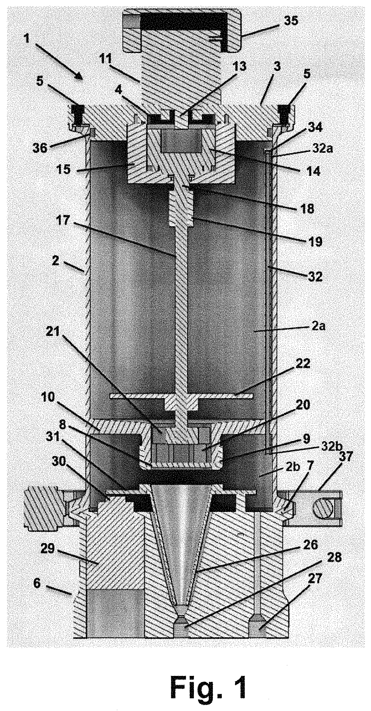
[0030]In general, the present invention relates to a powder-fluidizing apparatus and process for feeding ultra-fine powders, including nano-size materials, and for feeding powders with a broad particle size distribution, in a uniform manner over a long period of time. The powders are fed into applicators such as coating and spray forming nozzles and guns. The present invention is embodied in a powder-fluidizing apparatus and process that employ novel techniques for feeding the aforementioned types of powders. These techniques will now be described in detail.

[0031]FIG. 1...


PUM


Abstract

Powder fluidizing apparatus includes a unitary pressure vessel having a powder compartment and a transfer compartment, a lid on a first open end of the powder compartment and a base on a second end of the unitary pressure vessel, the second end sealing an open end of the transfer compartment. A plate separates the powder compartment from the transfer compartment, the plate being located between the lid and the base. A coupling collar secures a sieve disk packet in an opening in the plate. A tube extends from the transfer compartment to the powder compartment, the tube extending to a location near the lid of the unitary pressure vessel. When the transfer compartment is pressurized with a carrier gas, pressure in the transfer compartment and pressure in the powder compartment are equalized by the tube. The unitary pressure vessel is configured to contain the carrier gas in both the powder compartment and the transfer compartment and simultaneously perform as a reservoir for holding a quantity of powder in the powder compartment.

Description

[0001]This is a continuation of Provisional Application Ser. No. 62 / 676,416 filed May 25, 2018.INCORPORATION BY REFERENCE[0002]This application incorporates by reference in its entirety and for all purposes the disclosure of U.S. Pat. No. 7,273,075 B2 filed Feb. 7, 2006 and U.S. Pat. No. 6,915,964 filed Apr. 5, 2002.BACKGROUND1. Technical Field[0003]The present invention relates to a powder-fluidizing apparatus and process for feeding ultra-fine powders, including nano-size materials, and for feeding powders with a broad particle size distribution, in a uniform manner over a long period of time. The powders are fed into applicators such as coating and spray forming nozzles and guns.2. Background Art[0004]Several approaches currently exist for fluidizing powders. However, these approaches are designed for fluidizing larger particle sizes (e.g., particles larger than 635 mesh or 20 micrometers) and are not concerned with maintaining a consistent flow over a wide distribution of partic...

Claims


Application Information

Patent Timeline
Patent Type & Authority Patents(United States)
IPC IPC(8): B05B7/14B05B15/25B05C19/06B65B1/08
CPCB05B7/1445B05C19/06B05B15/25B05B7/1463B65B1/08
Inventor TAPPHORN, RALPH M.GABEL, HOWARD
Owner INNOVATION TECH INC
Why Eureka
Try Eureka