Disk fixing device

A fixing device and disc technology, which is used in measuring devices, instruments, surveying and mapping, and navigation, etc., can solve the problems of inability to adapt to larger parts, instrument fixation, and small movement range of clamping claws, so as to ensure connection strength and range of motion. big effect

Active Publication Date: 2014-09-24
扬州市双扬热处理有限公司
View PDF4 Cites 0 Cited by
  • Summary
  • Abstract
  • Description
  • Claims
  • Application Information

AI Technical Summary

Problems solved by technology

Most of the existing fixing devices are three claws, and the movement range of the clamping claws in the radial direction is small, which cannot adapt to the fixing of larger parts and instruments

Method used


Image

  • Disk fixing device
  • Disk fixing device
  • Disk fixing device

Examples


Embodiment Construction

[0017] The present invention will be specifically introduced below in conjunction with the accompanying drawings and specific embodiments.

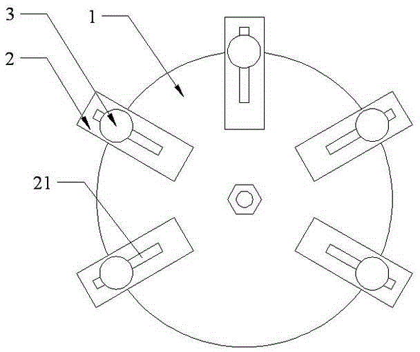
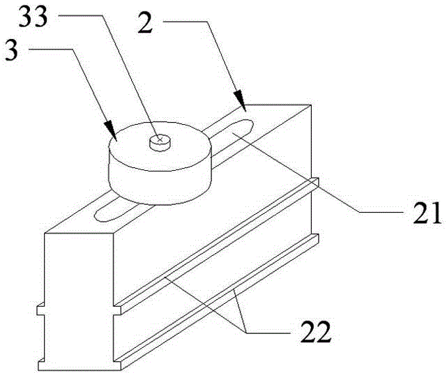
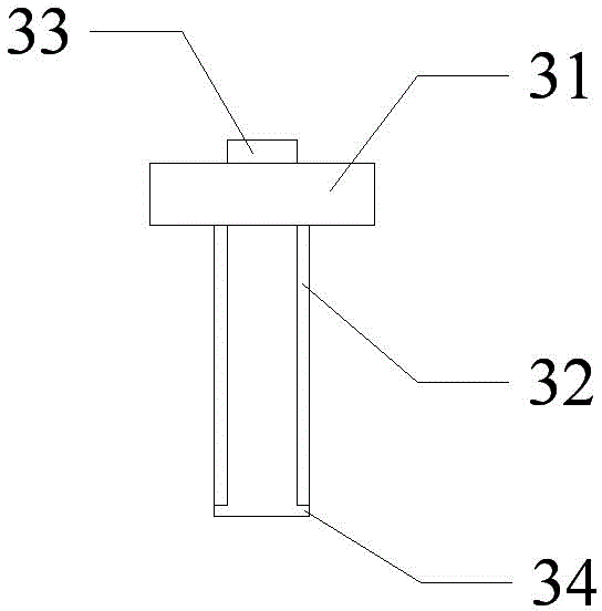
[0018] Such as figure 1 The disk fixing device shown includes: a disk 1, a plurality of sliding blocks 2 slidingly connected with the disk 1, and a clip 3 for clamping an object. Such as figure 2 As shown, the clamping member 3 is slidingly connected with the sliding block 2 , the top of the sliding block 2 is provided with a groove 21 for placing the clamping member 3 , and the grooves 21 are distributed along the length direction of the sliding block 2 . The sliding block 2 is provided with raised guide rails, the guide rails are distributed along the length direction of the sliding block 2, and the guide rails are located on both sides of the length direction of the sliding block 2, and the side of the disk 1 is provided with guide rail grooves that cooperate with the guide rails, and multiple guide rail grooves Distributed around t...


PUM


Abstract

The invention discloses a disk fixing device which comprises a disk, and a plurality of slide blocks in sliding connection with the disk; the disk fixing device is characterized by also comprising clamping pieces for clamping objects, wherein grooves for placing the clamping pieces are formed in the tops of the slide blocks, and the grooves are formed along the lengths of the slide blocks; each clamping piece comprises a contact part, an annular elastic part below the contact part, and a rotary screw in the annular elastic part, one end of the rotary screw penetrates through the top of the contact part, and the other end of the rotary screw is provided with a step part. The disk fixing device has the beneficial effects that the slide blocks slide on the disk so as to regulate the clamping range of the clamping pieces, the slide blocks are provided with the grooves which can be matched with the slide blocks, so that the clamping pieces move flexibly in a relatively large range, and the annular elastic part guarantees the connection strength of the clamping pieces and the grooves in the slide blocks, so that the device is tight in clamping.

Description

technical field [0001] The invention relates to the fixing of an optical surveying and mapping instrument, in particular to a disk fixing device with a plurality of clamping parts. Background technique [0002] In optical surveying and mapping, objects such as surveying instruments or objective lenses need to be fixed, and the cooperation between optical parts and instruments is very important, so the requirements for fixing each part or instrument are also very high. Most of the existing fixing devices are three claws, and the movement range of the engaging claws in the radial direction is small, which cannot adapt to the fixing of larger parts and instruments. Contents of the invention [0003] In order to solve the deficiencies of the prior art, the object of the present invention is to provide a disk fixing device with a wider adaptability. [0004] In order to achieve the above object, the present invention adopts the following technical solutions: [0005] The disk...

Claims


Application Information

Patent Timeline
Patent Type & Authority Applications(China)
IPC IPC(8): G01C15/00
CPCF16M11/04G01C15/00
Inventor 薛文英
Owner 扬州市双扬热处理有限公司
Why Eureka
Try Eureka