Bell-type furnace with a heat dispensing device positioned within a protective hood, in particular fed by an energy source external to the furnace chamber, for dispensing heat to annealing gas

A technology for annealing furnaces and protective covers, which can be used in bell-type furnaces, heat treatment furnaces, furnaces, etc., and can solve problems such as high energy consumption and heavy furnaces

Inactive Publication Date: 2014-10-01
EBNER-INDUSTRIEOFENBAU GMBH
View PDF7 Cites 0 Cited by
  • Summary
  • Abstract
  • Description
  • Claims
  • Application Information

AI Technical Summary

Problems solved by technology

[0005] Traditional furnaces are usually bulky and have relatively high energy consumption

Method used


Image

  • Bell-type furnace with a heat dispensing device positioned within a protective hood, in particular fed by an energy source external to the furnace chamber, for dispensing heat to annealing gas
  • Bell-type furnace with a heat dispensing device positioned within a protective hood, in particular fed by an energy source external to the furnace chamber, for dispensing heat to annealing gas
  • Bell-type furnace with a heat dispensing device positioned within a protective hood, in particular fed by an energy source external to the furnace chamber, for dispensing heat to annealing gas

Examples


Embodiment Construction

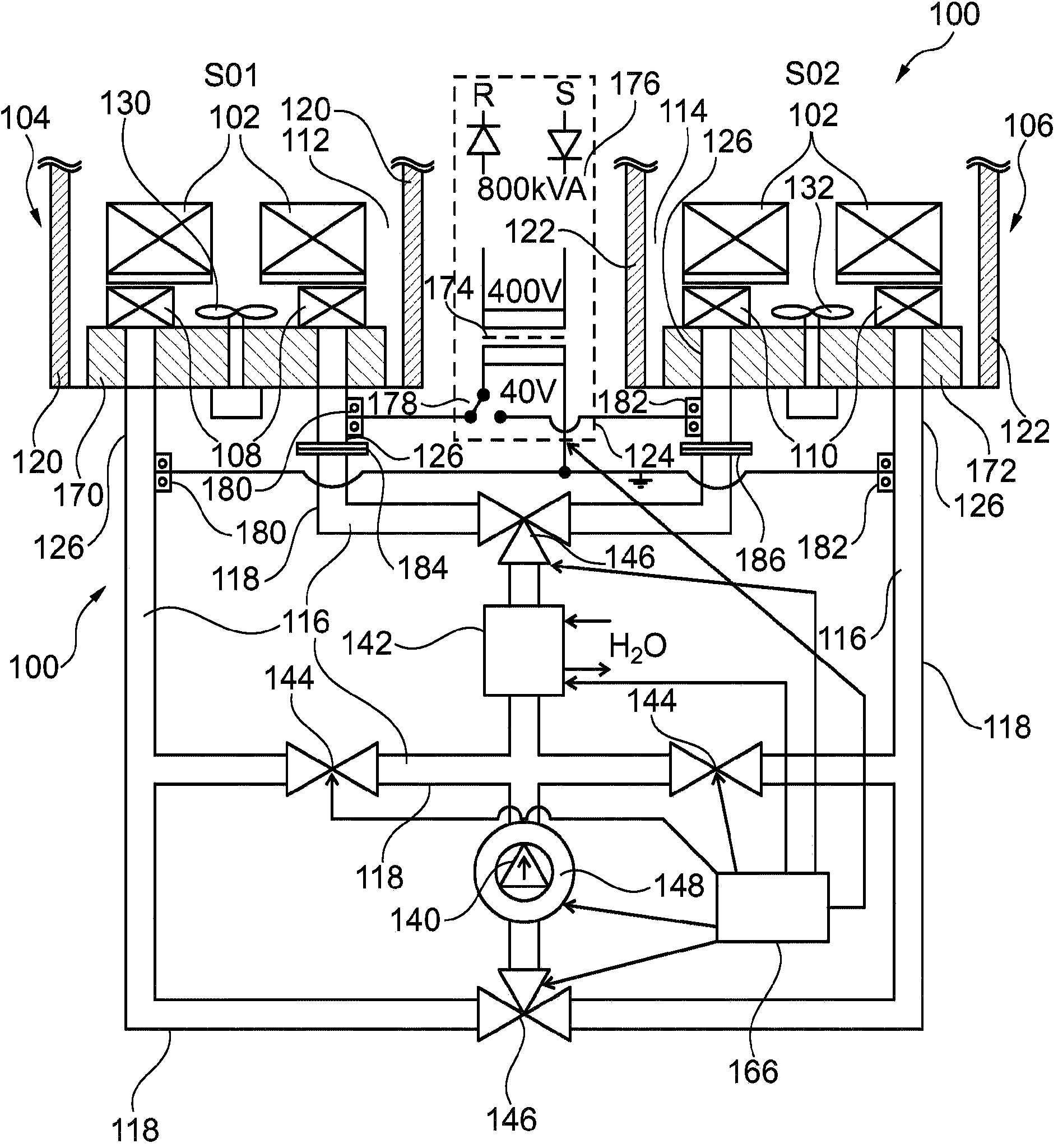
[0058] Below, refer to figure 1 Now, a bell furnace 100 according to an exemplary embodiment of the present invention will be introduced.

[0059] The bell furnace 100 is designed for the heat treatment of an annealing material 102 . The annealing material is arranged partly on the first bottom So1 of the bell furnace 100 and partly on the second bottom So2 of the bell furnace 100 . exist figure 1 The annealing material 102 , which is only schematically shown in , may for example be a coil of steel strip or wire rod or the like (for example a layered bulk material) which is to be subjected to heat treatment.

[0060] The bell furnace 100 has a first sealable furnace chamber 104 which is assigned to a first furnace bottom So1 . The first furnace chamber 104 is used for accommodating and heat-treating the annealing materials 102, and the annealing materials 102 are delivered to the first furnace bottom So1 in batches. For the heat treatment, the first furnace chamber 104 is ...


PUM


Abstract

A furnace (100) for the heat treatment of annealing stock (102), wherein the furnace (100) has a closeable first furnace chamber (104) which is designed for receiving and for the heat treatment of annealing stock (102) by means of thermal interaction of the annealing stock (102) with a heatable or coolable first annealing gas (112) in the first furnace chamber (104), and a removable first protective hood (120) by means of which the first furnace chamber (104) can be closed. Furthermore, a first heat exchange device (108) which is at least partially located in the interior of the first furnace chamber (104) closed by means of the first protective hood (120) is provided for heat exchange with the first annealing gas (112) within the first protective hood (120). The heat exchange device (108) is arranged in such a manner relative to a first annealing gas ventilator (130) for driving the annealing gas that, in each operating state of the furnace (100), the annealing gas driven by the first annealing gas ventilator (130) energizes the heat exchange device (100).

Description

technical field [0001] The invention relates to a furnace for the heat treatment of annealed material and to a method for the heat treatment of annealed material in the furnace. Background technique [0002] AT 508776 discloses a method for pre-warming the annealing material in a bell annealing apparatus having an annealing furnace floor below a protective hood containing the annealing material in a conveying fluid atmosphere. The annealed material to be heat-treated in the protective hood is preheated by means of a gaseous heat carrier, which in a circuit blows the protective hood from the outside and transfers heat from the annealed material that has been heat-treated in a protective hood The material is absorbed and output to the annealed material to be heat treated in another protective cover. For the heat treatment of the tempering material, at least one further tempering furnace floor is used which has a protective hood which can be heated from the outside by means of...

Claims


Application Information

Patent Timeline
Patent Type & Authority Applications(China)
IPC IPC(8): F27B11/00C21D9/677
CPCF27B11/00C21D9/0006C21D9/677F27D7/06F27D17/004
Inventor 罗伯特·艾伯纳海里伯特·洛赫纳
Owner EBNER-INDUSTRIEOFENBAU GMBH
Why Eureka
Try Eureka