Stress surface variable piston

A force-bearing surface and piston technology, used in non-mechanical drive clutches, fluid drive clutches, clutches, etc., can solve the problems of limited ability to improve clutch control characteristics and limited ability to quickly fill oil, and achieve reduced impact and mixed elastic modulus. Small changes and the effect of improving control performance

Active Publication Date: 2015-07-01
BEIJING INSTITUTE OF TECHNOLOGYGY
View PDF4 Cites 0 Cited by
  • Summary
  • Abstract
  • Description
  • Claims
  • Application Information

AI Technical Summary

Problems solved by technology

However, its rapid oil filling capability is limited and there is a certain degree of randomness, so the ability of this scheme to improve the control characteristics of the clutch is limited

Method used


Image

  • Stress surface variable piston
  • Stress surface variable piston
  • Stress surface variable piston

Examples


Embodiment Construction

[0024] The present invention will be described in detail below with reference to the accompanying drawings and examples.

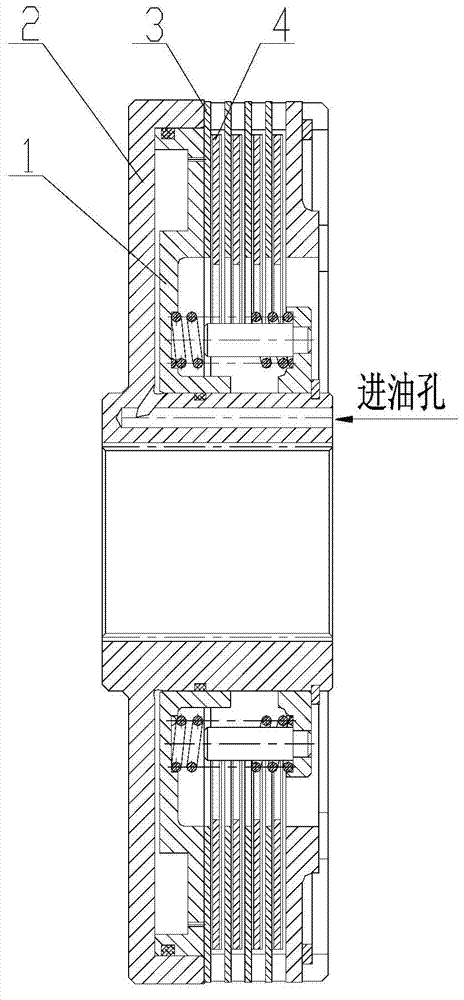
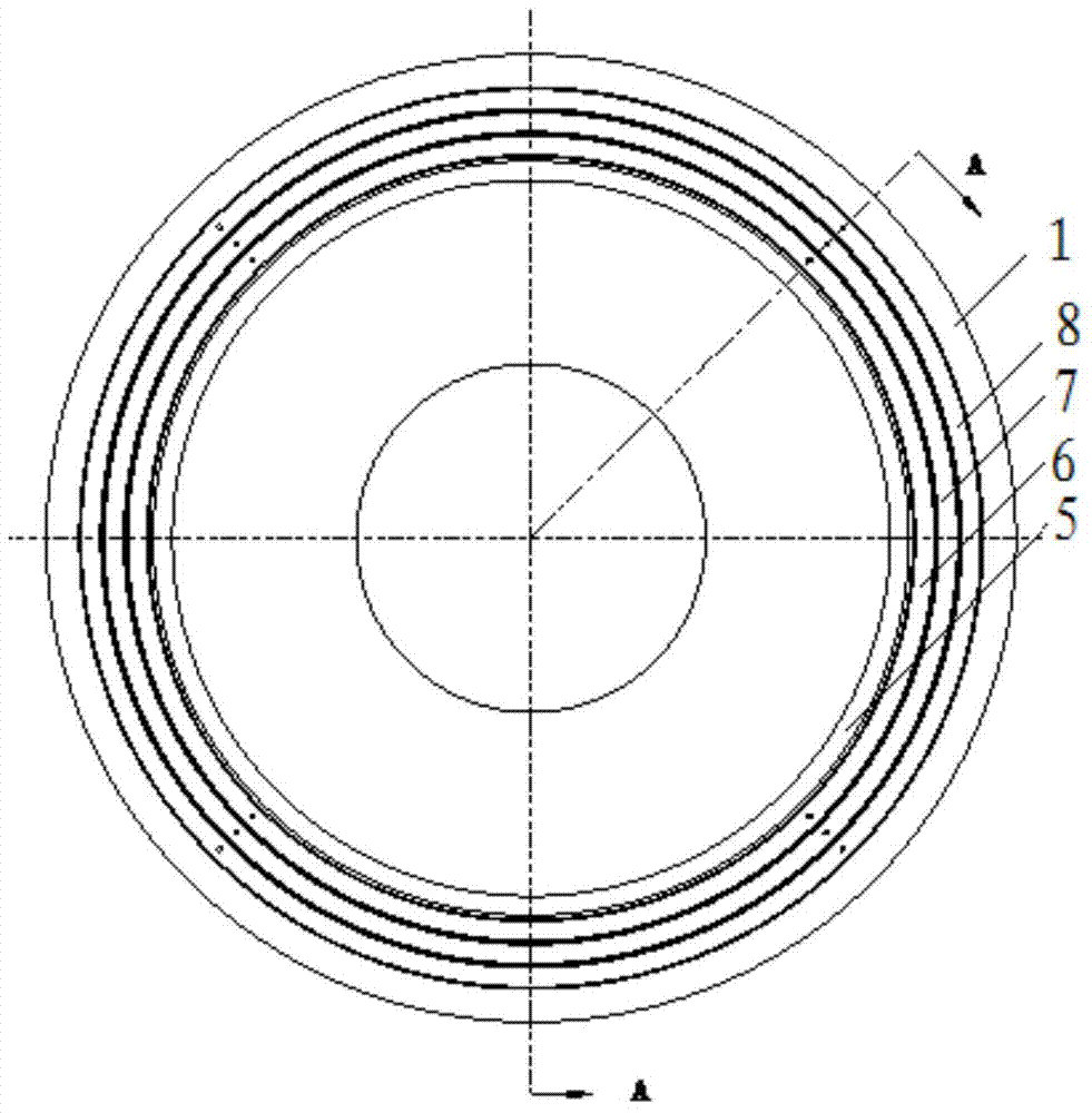
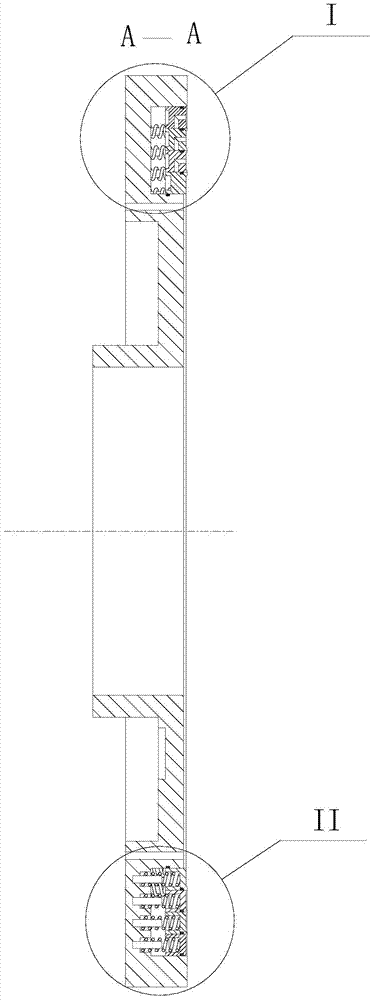
[0025] as attached figure 2 , 3 As shown in and 4, the present invention provides a piston with variable force bearing surface, including a piston body 1, a piston ring set, a spring 9 and a positioning pin 10; wherein, the piston ring set includes a piston ring I5, a piston ring II6, a piston The diameters of ring Ⅲ7 and piston ring Ⅳ8, piston ring Ⅰ5, piston ring Ⅱ6, piston ring Ⅲ7 and piston ring Ⅳ8 increase sequentially, and the end faces of the two ends of piston ring Ⅰ5 are the working surface and the installation surface respectively. The plane from the edge and concave, the plane extends to the inner circumferential surface of piston ring Ⅰ5; the working surface of piston ring Ⅱ6, piston ring Ⅲ7 and piston ring Ⅳ8 is the bottom surface of the annular groove on the end surface, piston ring Ⅱ6, piston ring L-shaped oil holes 11 are processed on Ⅲ7...


PUM


Abstract

The invention discloses a stress surface variable piston and belongs to the technical field of vehicle speed control systems. The stress surface variable piston comprises a piston body, a piston ring group, springs and positioning pins; a pressure-relief oil hole is machined in the end surface of the piston body; an oil discharge hole is machined in the bottom surface of a chamber body of the piston body; the piston ring group is formed by piston rings, wherein the diameters of the piston rings are gradually increased in turn; the working surface of the large diameter of piston ring is a plane which is formed from the edge of the end surface and is concaved inward; the working surface of every other piston ring is a bottom surface of an annular groove formed in the end surface; an L-shaped oil hole of every piston ring penetrates the inner circumferential surface of the piston ring and the bottom surface of the annular groove; the piston ring group is flexibly arranged in the chamber body of the piston body through the springs and the positioning pins; the piston rings are stepwise arranged according to the diameter size order in a sleeving mode in turn; elastic coefficients of the springs are increased in turn along with the increase of the diameters of the piston rings. According to the stress surface variable piston, the area of the piston is stepwise increased according to different oil pressure values when oil charge is performed on a piston cylinder and accordingly the unstable control caused by mixing of the oil and the gas in the chamber body can be reduced.

Description

technical field [0001] The invention relates to a vehicle transmission system, in particular to a piston of a wet friction clutch, and belongs to the technical field of vehicle transmission systems. Background technique [0002] The combination of the clutch friction pair in the vehicle transmission system needs to be realized by controlling the pressure of the oil on the piston, so the pressure characteristics of the control oil pressure play a decisive role in the quality of clutch control. The characteristics of clutch pressure building mainly depend on the structure of the clutch and the control strategy of the control oil valve. During the oil filling process of the clutch, due to the uncertainty of the state of oil and gas in the piston cavity, sometimes there is a big discrepancy between the theoretical control characteristics and the actual control characteristics. Secondly, during the process of clutch engagement and disengagement, oil pressure needs to be quickly ...

Claims


Application Information

Patent Timeline
Patent Type & Authority Patents(China)
IPC IPC(8): F16D25/12
Inventor 李和言何松
Owner BEIJING INSTITUTE OF TECHNOLOGYGY
Why Eureka
Try Eureka