Generator temperature control device
A technology of temperature control device and generator, which is applied in the direction of temperature control using electric mode, auxiliary controller with auxiliary heating device, etc., can solve problems such as failure, low work efficiency, and high labor intensity of staff, and achieve The effect of power maximization
- Summary
- Abstract
- Description
- Claims
- Application Information
AI Technical Summary
Problems solved by technology
Method used
Image

Examples
Embodiment 1
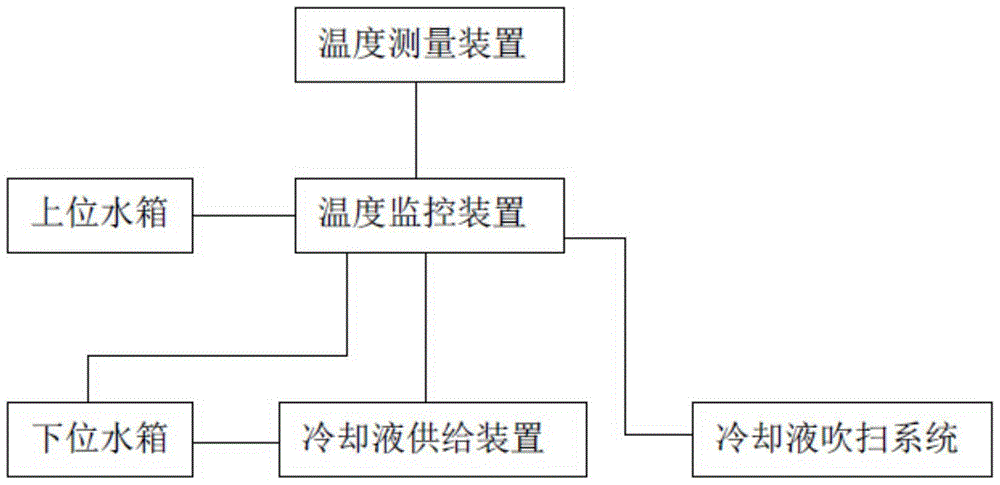
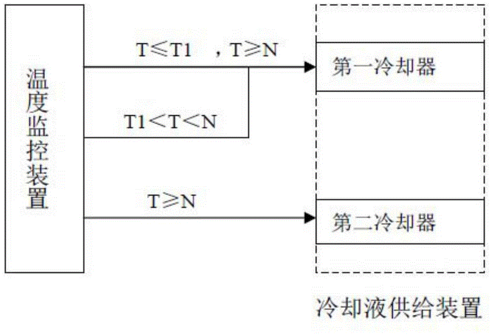
[0031] The generator temperature control device provided in this embodiment, such as Figure 1-2 As shown, including: cooling liquid supply device, temperature measuring device, temperature monitoring device for comparing the working temperature T with the normal working temperature T1;
[0032] Manually set the normal operating temperature T1 according to the performance requirements of the generator, the operating temperature T is the temperature of the generator rotor, the temperature measuring device performs cyclic measurement of the temperature of the generator rotor, the normal operating temperature T1, set manually before it starts working;
[0033] The cooling liquid supply device includes a first cooler and a second cooler, and the first cooler and the second cooler have respective independent cooling circuits.
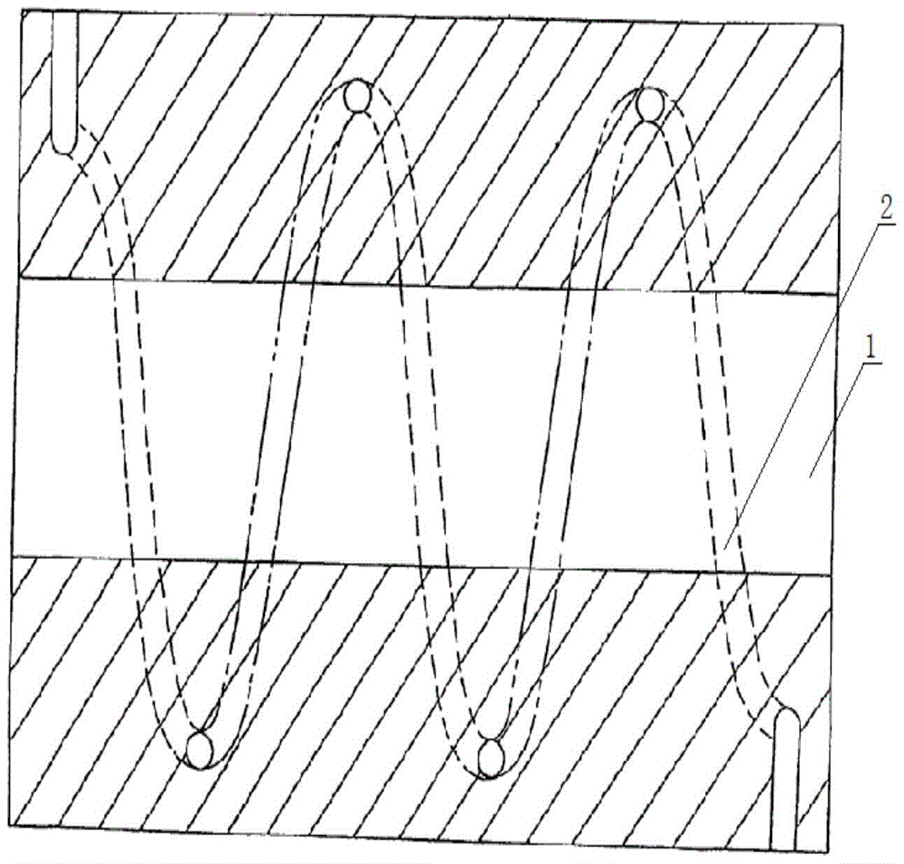
[0034] The first cooler is sealed and circulated with the first coolant, and the first cooling device includes a first inflow pipeline, a plurality of firs...
Embodiment 2
[0043] Such as figure 1 As shown, the temperature control device of the generator is equipped with an upper water tank and a lower water tank. The function of the upper water tank is to inject coolant into the coolant circulation system, and also to supplement the lack of coolant to the coolant circulation system. The lower water tank controls the amount of coolant in the coolant circulation system within a certain range. A liquid level gauge is installed on the lower water tank, and the liquid level gauge outputs a signal and an alarm signal that the upper water tank injects the first cooling liquid and the second cooling liquid when the cooling liquid is lower than the warning liquid level. When the warning liquid level is exceeded, the output signal is stopped, and the upper water tank stops injecting the first and second cooling liquids. The first and second coolants of the upper water tank are injected manually before the engine starts to work.
Embodiment 3
[0045] Such as figure 1 As shown, after the generator test system is connected to the generator, the cooling (water) fluid (the first coolant and the second coolant) is filled from the upper water tank to the coolant circulation system, and the coolant is sucked by the generator after the generator is running. Through the outlet of the generator, the first manual ball valve, the first pneumatic ball valve, the check valve, the first or second cooler, the first pneumatic ball valve, and the first manual ball valve go to the generator inlet to form a cycle.
PUM
 Abstract
Description
Claims
Application Information
 - R&D
- Intellectual Property
- Life Sciences
- Materials
- Tech Scout
- Unparalleled Data Quality
- Higher Quality Content
- 60% Fewer Hallucinations
Browse by: Latest US Patents, China's latest patents, Technical Efficacy Thesaurus, Application Domain, Technology Topic, Popular Technical Reports.
© 2025 PatSnap. All rights reserved.Legal|Privacy policy|Modern Slavery Act Transparency Statement|Sitemap|About US| Contact US: help@patsnap.com