Eureka AIR delivers breakthrough ideas for toughest innovation challenges, trusted by R&D personnel around the world.

Cable sleeve

A technology of cable bushing and semi-cylindrical tube, applied in electrical components and other directions, can solve the problems of narrow structure and installation space, difficulty in erecting and aligning steel pipes, and difficulty in penetrating into the mechanism box, so as to increase safety and reliability and avoid insulation performance. Drop or even short circuit, the effect of simple structure

Inactive Publication Date: 2014-10-08
STATE GRID CORP OF CHINA +1
View PDF5 Cites 6 Cited by
  • Summary
  • Abstract
  • Description
  • Claims
  • Application Information

AI Technical Summary

Problems solved by technology

In the cable casing protection equipment used in the prior art, it is very difficult to pull out due to too many cables penetrated or because the cables are thick, and it is difficult to straighten the steel pipe during the process of standing up after being penetrated into the steel pipe. It needs to be adjusted after being erected, but sometimes due to the narrow structure and installation space, it is very difficult to erect and straighten the steel pipe, which makes it very difficult to penetrate the mechanism box and the work efficiency is low, so it is necessary to facilitate the direct penetration of the cable before use sleeve to protect the cable

Method used


Image

  • Cable sleeve
  • Cable sleeve
  • Cable sleeve

Examples


Embodiment Construction

[0022] In order to better understand the present invention, the implementation manner of the present invention will be explained in detail below in conjunction with the accompanying drawings.

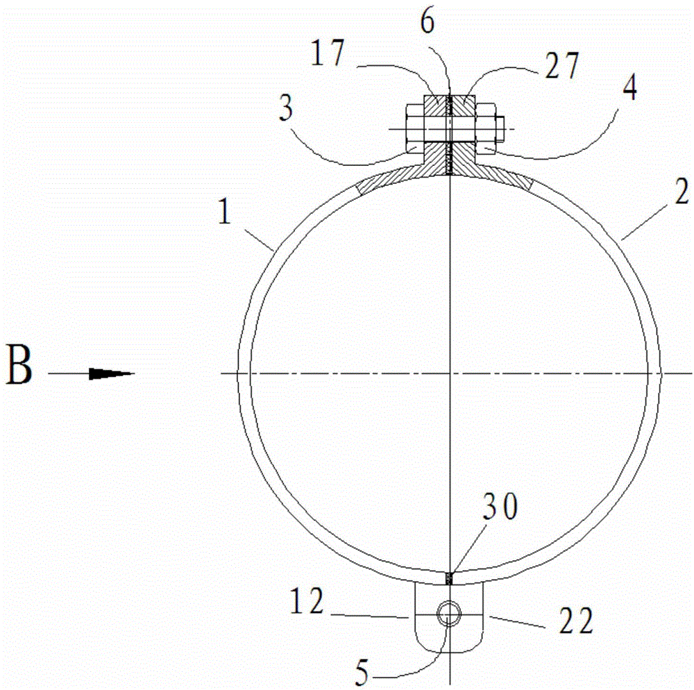
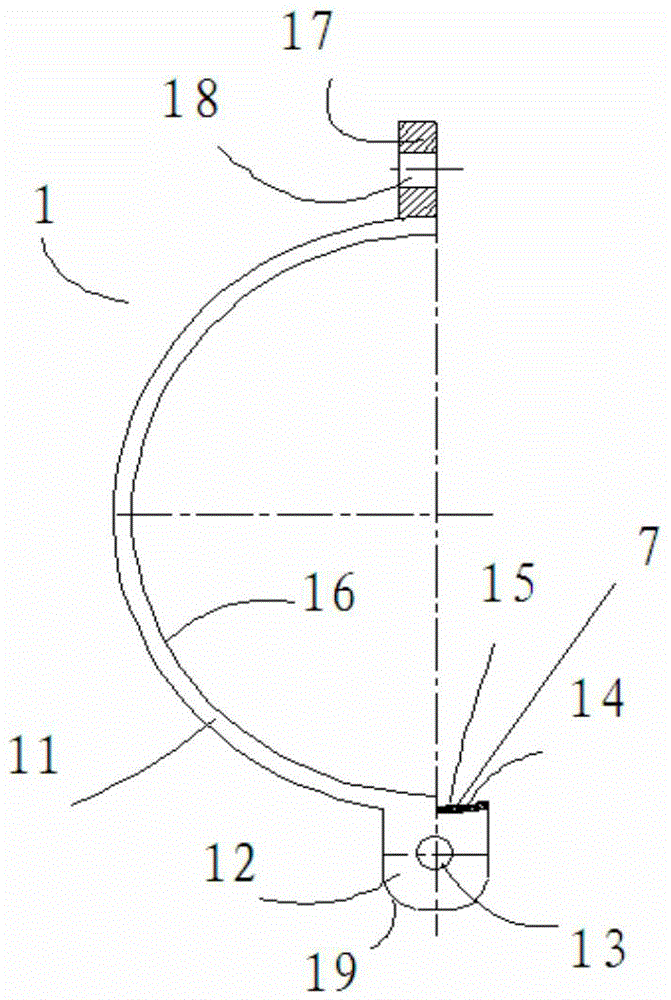
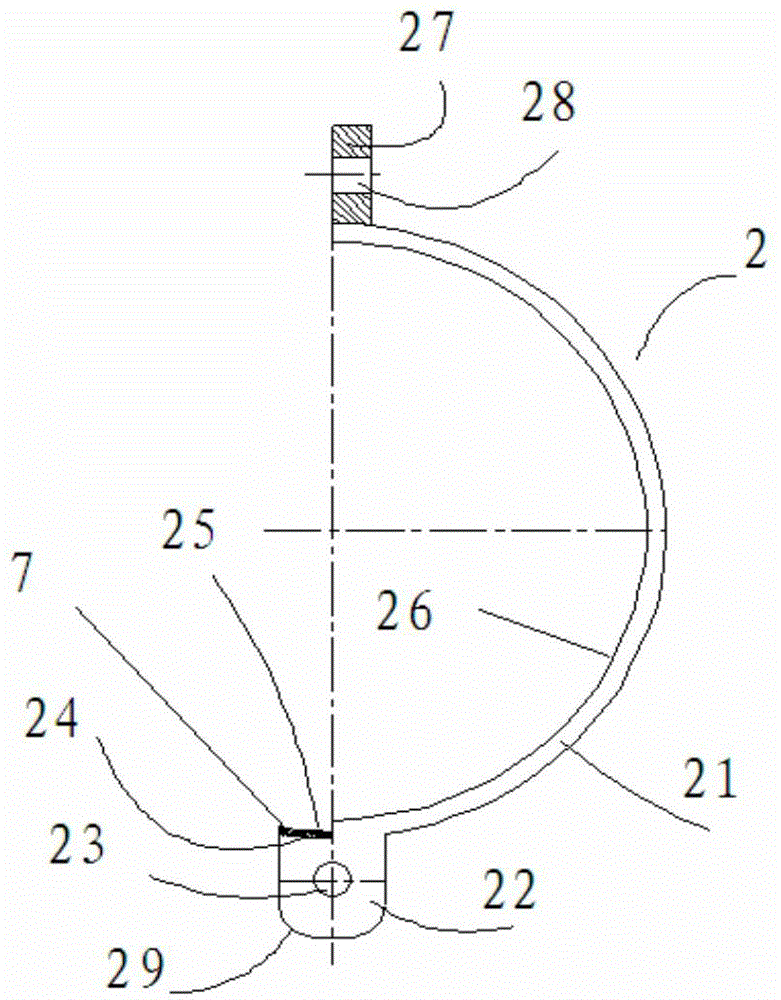
[0023] combine Figure 1 to Figure 5 , a cable sleeve, comprising a first semi-cylindrical tube 1 of equal diameter and a second semi-cylindrical tube 2 connected, the opening position of the lower part of the first semi-cylindrical 1 is provided with a first outer cylindrical surface 11 connected The first fixing plate 12, the first fixing plate 12 is provided with the first connecting hole 13 parallel to the axis of the first semi-cylindrical tube 1, the opening position of the upper part of the first semi-cylindrical is provided with the first connecting hole 13 connected with the outer cylindrical surface A connecting plate 17, the first connecting plate 17 is provided with the third connecting hole 18 perpendicular to the axis of the first semi-cylindrical tube 1; The second fixed...


PUM


Abstract

The invention discloses a cable sleeve which comprises two semi-cylindrical pipes. The lower portion of the first half cylinder is provided with a first fixing plate, the first fixing plate is provided with a first connecting hole, the upper portion of the first half cylinder is provided with a first connecting plate connected with the outer cylindrical surface, and the first connecting plate is provided with a third connecting hole perpendicular to the axis of the first semi-cylindrical pipe. The lower portion of the second half cylinder is provided with a second fixing plate connected with the second outer cylindrical surface, the second fixing plate is provided with a second connecting hole, the upper portion of the second half cylinder is provided with a second connecting plate connected with the outer cylindrical surface, and the second connecting plate is provided with a fourth connecting hole perpendicular to the axis of the second semi-cylindrical pipe. The third connecting hole and the fourth connecting hole are connected through a bolt and a nut, the first fixing plate and the second fixing plate are connected through a connecting shaft, and the first semi-cylindrical pipe and the second semi-cylindrical pipe are hinged though a connecting shaft. The cable sleeve is simple in structure, high in safety reliability and convenient to use, install and dismount, facilitates steel pipe erection, placement and adjustment after a cable penetrates a steel pipe and improves the working efficiency.

Description

technical field [0001] The invention relates to the technical field of cable protection facilities, in particular to a new type of cable sleeve used for protecting the part of the cable exposed in the air from a cable trench to a switch mechanism box or a CT mechanism box. Background technique [0002] Cable laying is an important task in relay protection work. During the cable laying process, since the cables passing through the cable trench to the switch mechanism box are exposed to the air and are easily damaged, they need to be inserted into a steel pipe. to protect the cable. In the cable casing protection equipment used in the prior art, it is very difficult to pull out due to too many cables penetrated or because the cables are thick, and it is difficult to straighten the steel pipe during the process of standing up after being penetrated into the steel pipe. It needs to be adjusted after being erected, but sometimes due to the narrow structure and installation space...

Claims


Application Information

Patent Timeline
Patent Type & Authority Applications(China)
IPC IPC(8): H02G3/04
Inventor 陈浙杜嘉寅王志强于光远
Owner STATE GRID CORP OF CHINA
Why Eureka
Eureka Blog
Learn More