Device for compressing the transfer element

A technology of transmitting elements and elastic elements, applied in the direction of transmission, friction transmission, hoisting device, etc.

Inactive Publication Date: 2016-07-06
ZF LENKSYSTEME GMBH
View PDF6 Cites 0 Cited by
  • Summary
  • Abstract
  • Description
  • Claims
  • Application Information

AI Technical Summary

Problems solved by technology

However, attempts to solve this problem by elastic elements with increased elastic force did not lead to satisfactory results, since this increased elastic force simultaneously requires an increased driving force for moving the rack

Method used


Image

  • Device for compressing the transfer element
  • Device for compressing the transfer element
  • Device for compressing the transfer element

Examples


Embodiment Construction

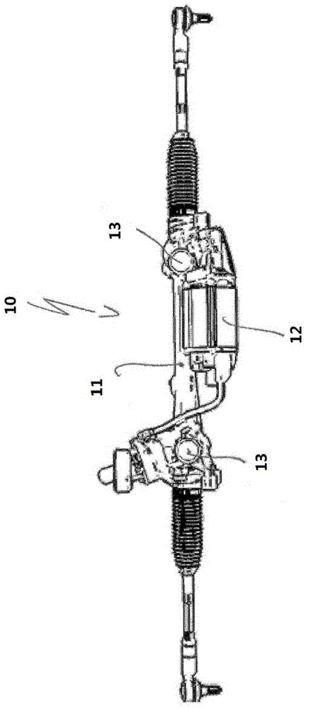
[0027] figure 1 Shown is a steering mechanism 10, in particular an electric steering mechanism, for a motor vehicle, with a housing area 11 behind which the rack is concealed, and a housing area 12 behind which the electric motor is mounted ; Devices 13 for pressing the rack against two pinions not shown in detail here. The toothed rack corresponds to the first transmission element and the pinion corresponds to the second transmission element.

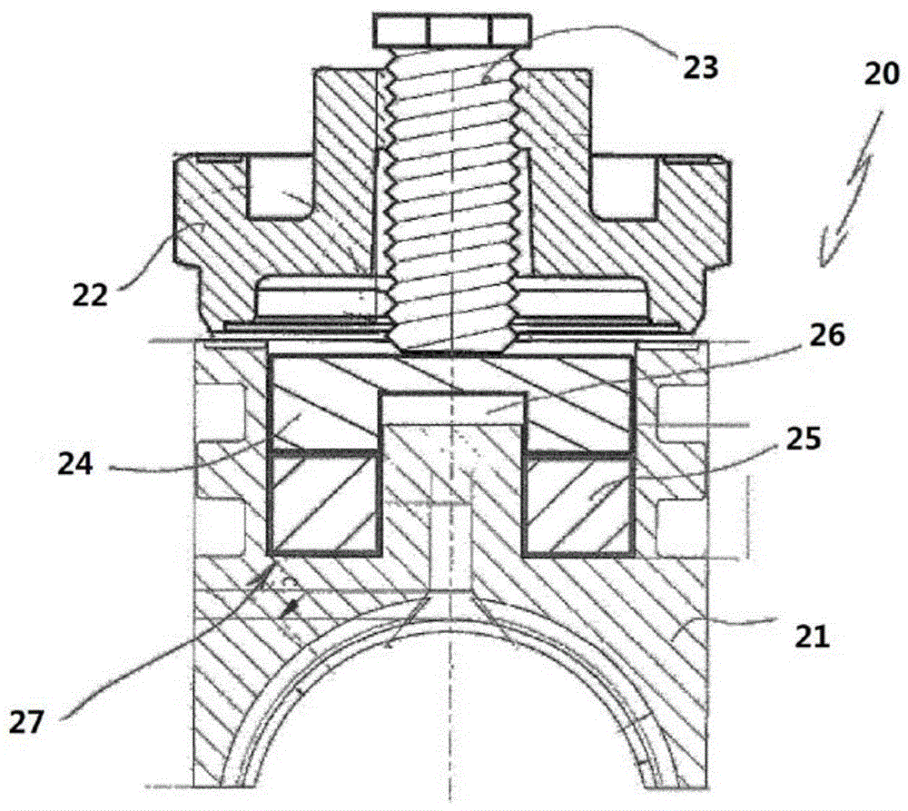
[0028] figure 2 Means 20 for pressing the rack onto the pinion are shown. The device 20 has a pressure piece 21 against which an adjusting screw 22 is pressed. The adjusting screw 22 has an external thread, not shown in detail here, with which the adjusting screw can be screwed into a housing, also not shown, in which the pressure piece 21 is guided.

[0029] A set screw 23 is screwed into the adjusting screw 22 and is pressed against the cover 24 . Said cover 24 is pressed against an elastic element 25 made of expanded elastomer...


PUM


Abstract

The invention relates to a device ( 20 ) for pressing a first transmission element onto a second transmission element embedded in the first transmission element, in particular for a rack-type steering gear of a motor vehicle, which The device has a pressure block ( 21 ) that can be loaded in the direction of the first transmission element by at least one elastic element ( 25 ), which is guided in a housing so as to be movable, wherein the elastic element ( 25 ) is formed by at least one elastic element ( 25 ) Made of an expanded elastomer.

Description

technical field [0001] The invention relates to a device for pressing a first transmission element onto a second transmission element which engages in said first transmission element, said device being used in particular for a rack-and-pinion steering of a motor vehicle, the device having A pressure piece which is guided displaceably in the housing is loadable by at least one spring element in the direction of the first transmission element. Background technique [0002] In devices of this type known from the prior art, helical springs are used for the elastic element. The purpose of the helical spring is to press the toothed rack against the pinion during driving operation, so that unwanted noises can be avoided. This noise can be generated either in the contact area between the pressure piece and the adjusting bolt when the steering wheel is turned quickly back and forth, or when driving over rough roads and between the pressure piece and the rack or between the rack and ...

Claims


Application Information

Patent Timeline
Patent Type & Authority Patents(China)
IPC IPC(8): B62D3/12F16H55/28
CPCB62D3/123F16H55/283Y10T74/18096F16H19/04
Inventor 格尔德·施派德尔赖纳·尚策尔托马斯·阿尔伯尔
Owner ZF LENKSYSTEME GMBH
Why Eureka
Try Eureka