Cover assembly with axially pretensioned wire ring for a clutch and clutch with such a cover assembly

A technology of assemblies and wire rings, applied in the direction of clutches, friction clutches, mechanically driven clutches, etc., can solve the problems of unsuitability and limitation of motor vehicles, achieve the maximum operating force that remains unchanged for a long time, improve noise characteristics, prevent noise effect

Active Publication Date: 2018-12-21
SCHAEFFLER TECH AG & CO KG
View PDF5 Cites 0 Cited by
  • Summary
  • Abstract
  • Description
  • Claims
  • Application Information

AI Technical Summary

Problems solved by technology

[0014] Overall, the known solutions are unsuitable or only very limitedly suitable for cost-effective motor vehicles

Method used


Image

  • Cover assembly with axially pretensioned wire ring for a clutch and clutch with such a cover assembly
  • Cover assembly with axially pretensioned wire ring for a clutch and clutch with such a cover assembly
  • Cover assembly with axially pretensioned wire ring for a clutch and clutch with such a cover assembly

Examples


Embodiment Construction

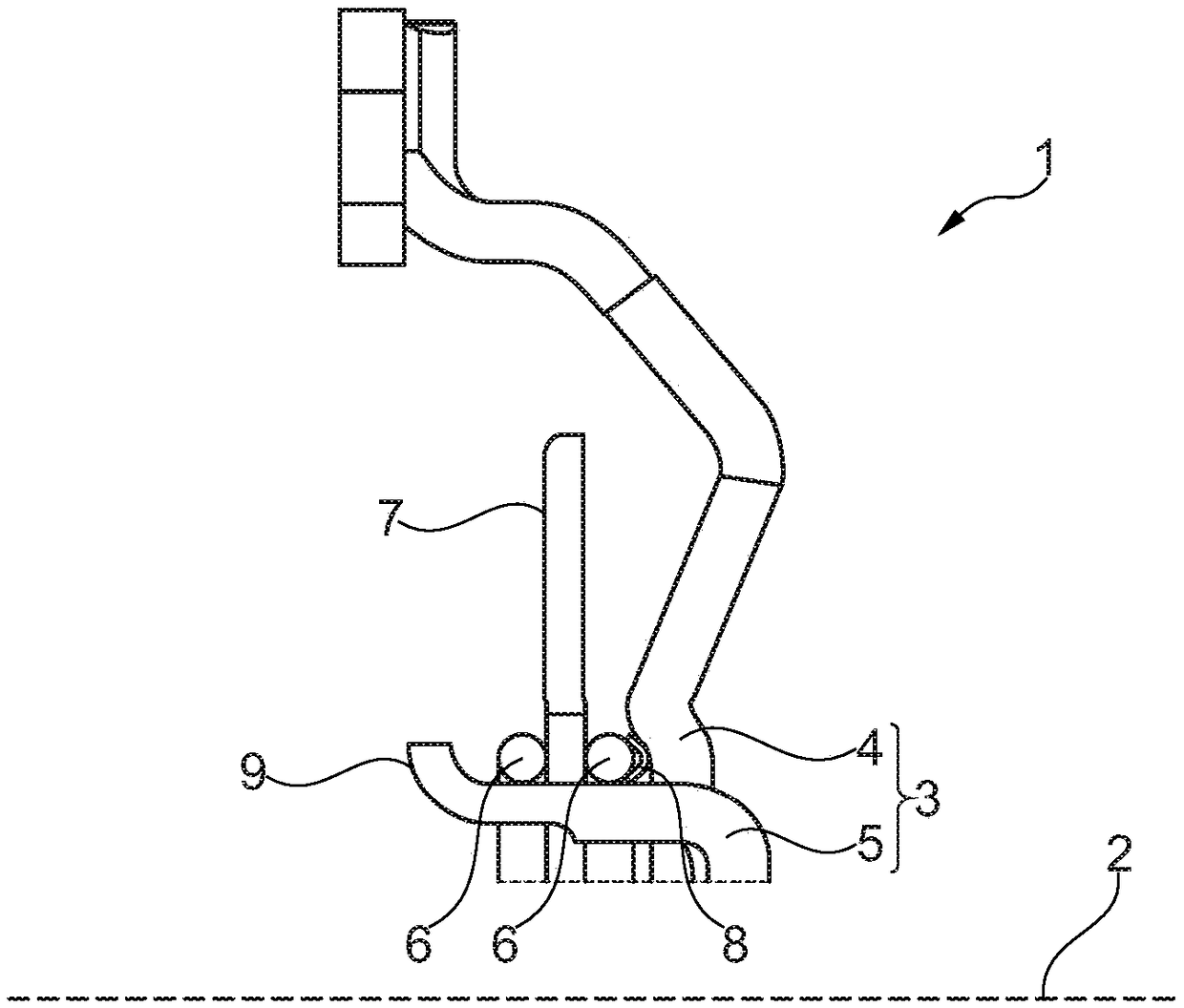
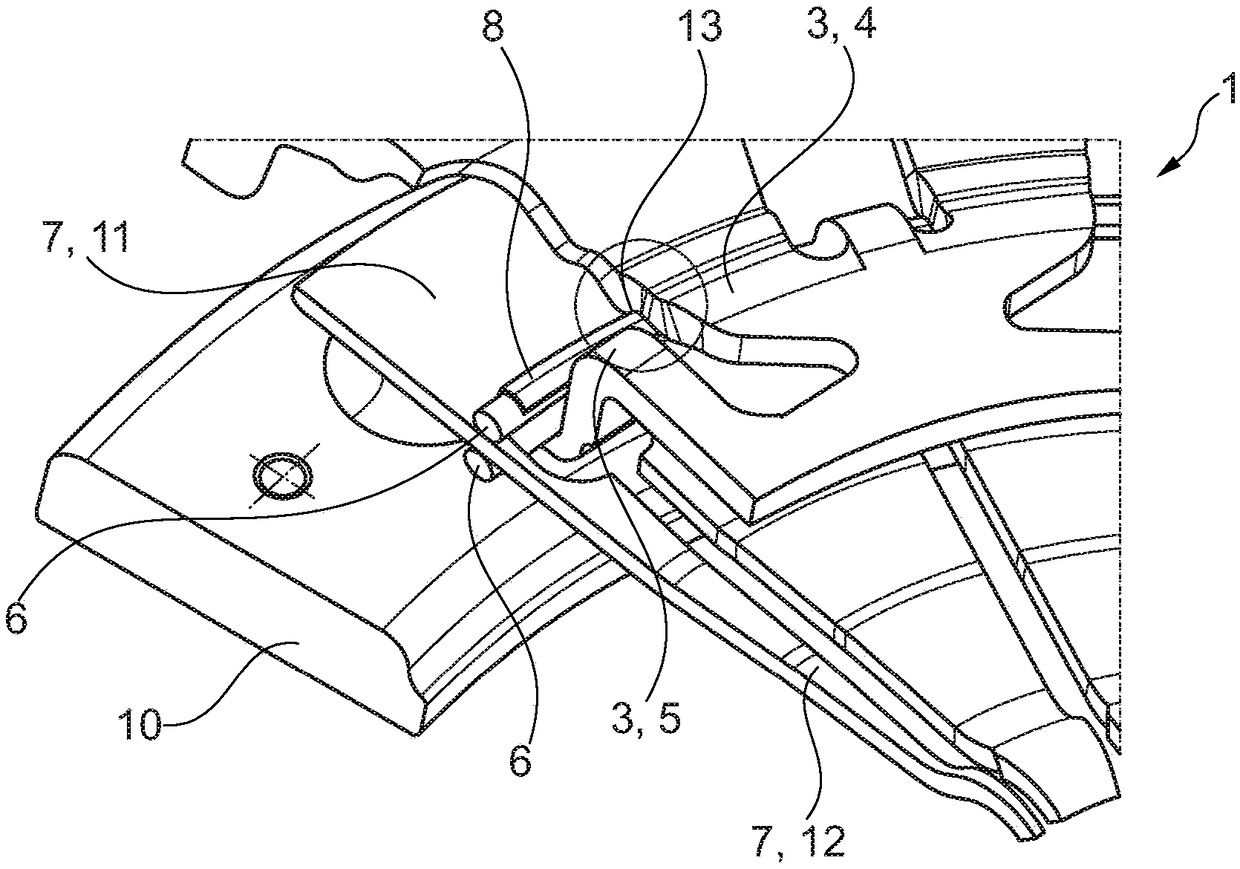
[0047] Figures 1 to 5 A cover assembly 1 according to a first embodiment of the invention is shown. exist figure 1 It can be seen in the cover assembly 1 in a sectional view parallel to the axial direction or displacement direction 2 .

[0048] figure 1 Cover 3 is shown in . The cover 3 is a molded member. In particular, the cover section 4 and the holding section 5 are shown, both of which are formed in one piece from the sheet metal part forming the cover 3 by means of sheet metal forming. Arranged radially outside the holding section 5 are two wire rings 6 , a disk spring 7 and a spring element 8 . The spring element 8 is currently arranged between the cover-side wire ring 6 and the cover section 4 , ie at figure 1 On the side of the right-hand wire loop 6 facing away from the disc spring 7 . The disc spring 7 is an actuating element within the meaning of claim 1 .

[0049] The holding section 5 extends substantially away from the cover section 4 in the axial direc...


PUM


Abstract

The invention relates to a cover assembly (1) for a motor vehicle clutch, said assembly comprising an actuating element (7), such as a diaphragm spring, said element being provided to come into contact with a pressure plate (10), the actuating element (7) being in contact with a cover (3) via at least one wire ring (6). At least one spring element (8), the cross-section of which is substantially V-shaped when unstressed and substantially C-shaped when pre-stressed, lies on the wire ring (6) in order to pre-stress said wire ring (6) in an axial direction, such that during the pre-stressing process limbs of the substantially V-shaped cross-section slide along an external surface of the wire ring (6) during the transition into the substantially C-shaped cross-section.

Description

technical field [0001] The invention relates to a cover assembly for a clutch / friction clutch of a motor vehicle, with an actuating element, such as a disk spring, which is intended to come into contact with a pressure plate, wherein the actuating element is connected to the cover via at least one wire loop cling to. Background technique [0002] Clutches are generally used in the drive train of a motor vehicle to couple an internal combustion engine to at least one drive wheel or to decouple it from said drive wheel. For this purpose, a clutch is usually arranged between an output shaft of the internal combustion engine, such as a crankshaft, and an input shaft of a transmission, which is operatively connected to at least one drive wheel. Usually the pressure plate is connected in a rotationally fixed manner to the crankshaft. Usually the clutch disk is connected to the transmission input shaft in a rotationally fixed manner and in an axially displaceable manner. The clu...

Claims


Application Information

Patent Timeline
Patent Type & Authority Patents(China)
IPC IPC(8): F16D13/58F16D13/71
CPCF16D13/585F16D13/71
Inventor J·罗伊R·马尼R·伦加萨米
Owner SCHAEFFLER TECH AG & CO KG
Why Eureka
Try Eureka