An automatic feeding mechanism

An automatic feeding and material path technology, which is applied in the direction of automatic in/out of workpieces, automatic/semi-automatic lathes, mechanical equipment, etc., can solve the problems of complex control system, billet congestion, poor production continuity, etc., and achieve simple control system and systematic Good stability, avoiding the effect of poor production continuity

CN104096863BActive Publication Date: 2017-08-25浙江陀曼智能科技股份有限公司
8 Cites 0 Cited by

Patent Information

Authority / Receiving Office
CN · China
Patent Type
Patents(China)
Current Assignee / Owner
Publication Date
2017-08-25

Smart Images

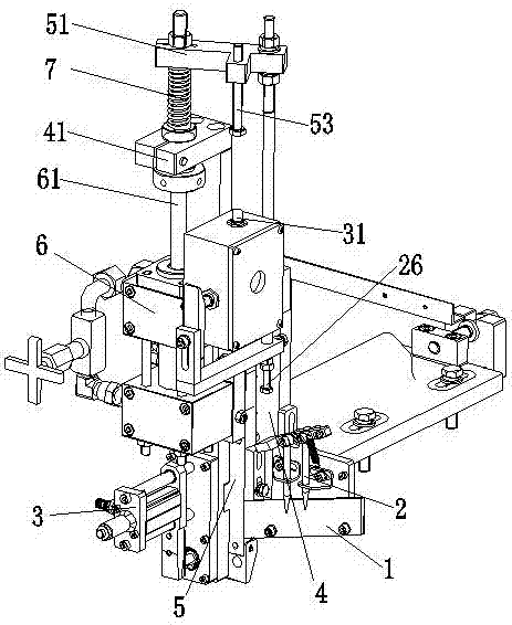
  • Figure 1
    Figure 1
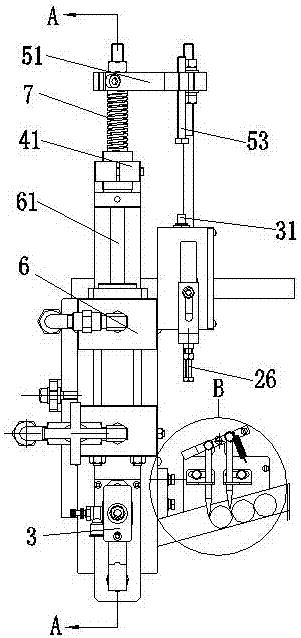
  • Figure 2
    Figure 2
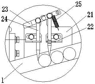
  • Figure 3
    Figure 3
Patent Text Reader

Abstract

The invention discloses an automatic feed mechanism matched with a hydraulic lathe for use when the hydraulic lathe is used for machining workpieces with shorter axial length, such as micro bearing rings and micro bearing shaft sleeves. The automatic feed mechanism comprises a material passage, a fixed support and a movable support, wherein the movable support and the fixed support are in sliding connection, the lower end of the movable support is provided with a workpiece pressing device, the lower part of the movable support is provided with a material accommodating cavity which is provided with an inlet communicated with the material passage and an outlet corresponding to a lathe clamping device, the axes of the outlet of the material accommodating cavity, the lathe clamping device and the workpiece pressing device are collinear, the material passage is obliquely arranged, and a material blocking device is also arranged on the material passage. In one working circulation, only one workpiece enters the material accommodating cavity and is fed into the lathe clamping device, the structure is simple, the number of fed materials and the starting of the workpiece pressing device are controlled by the structure per se, and the defects that the production is interrupted caused by the fact that materials are easily blocked, and the stability of a control system is poor due to the complexity of the control system in the prior art are effectively overcome.
Need to check novelty before this filing date? Find Prior Art

Description

technical field

[0001] The invention relates to the field of automatic processing of hydraulic lathes, in particular to an automatic feeding mechanism used in conjunction with hydraulic lathes when processing workpieces with short axial lengths such as miniature bearing rings and miniature bushings. Background technique

[0002] When machining a workpiece on a hydraulic lathe, it is first necessary to place the blank on the clamping mechanism of the spindle, and then perform turning after clamping the workpiece. At present, there are two main loading methods for placing workpieces on the clamping mechanism: manual loading and automatic loading. Manual loading is inefficient, especially in automated production lines, where manual loading is completely abandoned.

[0003] The Chinese invention patent with the application number "201010119959.9" discloses an automatic feeding device for CNC lathes, which is mainly driven by a hopper installed on the bedside box, and the hopper ...

Examples

Embodiment Construction

[0023] The automatic feeding mechanism of this embodiment will be further described in detail below in conjunction with the accompanying drawings and specific implementation methods.

[0024] A kind of automatic feeding mechanism of this embodiment, such as figure 1 , figure 2 , Figure 4 As shown, it includes a material channel 1, a fixed support 4 and a movable support 5. Wherein, the movable support 5 is slidably connected with the fixed support 4 in the vertical direction, and the way of the slidable connection adopts any one in the prior art that can realize relative sliding up and down.

[0025] The lower end of the above-mentioned movable support 5 is provided with a pressing device 3 for pressing the workpiece into the lathe clamping device. The inlet connected to the road 1 and the outlet corresponding to the clamping device of the lathe, the outlet of the above-mentioned material chamber 52, the axes of the clamping device of the lathe and the pressing device 3 a...