A quick release valve built-in diaphragm and quick release valve

A diaphragm and body technology, which is applied in the field of quick release valve built-in diaphragm and quick release valve, can solve the problems of taking up a lot of space, high cost, and unable to reduce howling, so as to reduce the generation of high frequency vibration and reduce the concentration of force Effect

Active Publication Date: 2017-04-12
ANHUI JIANGHUAI AUTOMOBILE GRP CORP LTD
View PDF6 Cites 0 Cited by
  • Summary
  • Abstract
  • Description
  • Claims
  • Application Information

AI Technical Summary

Problems solved by technology

Such technology is useful for reducing the exhaust noise of the quick-release valve, but it can only reduce the airflow noise generated when the exhaust port is exhausted when the brake is released, and cannot reduce the high-frequency vibration of the diaphragm 4 during braking. Howling
And after the damping device 8 is installed, there are many problems such as taking up a lot of space and high cost

Method used


Image

  • A quick release valve built-in diaphragm and quick release valve
  • A quick release valve built-in diaphragm and quick release valve
  • A quick release valve built-in diaphragm and quick release valve

Examples


Embodiment 1

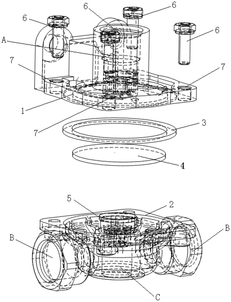
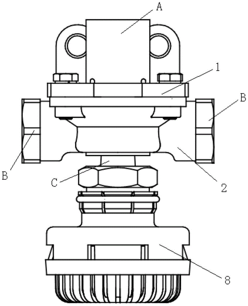
[0041] Such as Figure 4 to Figure 7 As shown, a quick-release valve includes a built-in diaphragm of the quick-release valve, an upper casing, a lower casing, an air release valve, a sealing ring and fastening bolts; the quick-release valve of the present application is only for the existing The diaphragm of the quick-release valve is structurally improved, and the damping equipment is omitted, and other structures of the quick-release valve are the same as the prior art.

[0042] An air inlet is provided on the upper casing, and four screw holes are arranged on the upper casing for passing fastening bolts; the air inlet is connected with an air source.

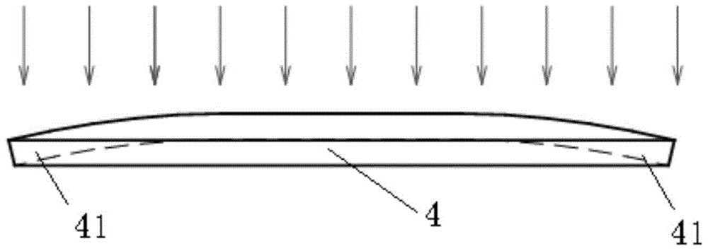
[0043] The built-in diaphragm of the quick-release valve includes a diaphragm body 101, and a first boss structure 111 is arranged on the upper surface of the diaphragm body 101; The centers coincide.

[0044] On the upper surface of the diaphragm body 101, from the circumscribed circle of the first boss structure 111 to t...

Embodiment 2

[0054]In other embodiments of the present application, other parts of the quick release valve body are the same as in embodiment 1, and only the structure of the built-in diaphragm of the quick release valve is improved. Therefore, in the following embodiments, only the quick release valve is described Structure of built-in touch pads.

[0055] The built-in diaphragm of the quick-release valve is made of rubber or polymer material or polyester material, and includes a diaphragm body, and a first boss structure is arranged on the upper surface of the diaphragm body; the first boss structure The center coincides with the center of the diaphragm body;

[0056] The diameter of the circumscribed circle of the first boss structure is smaller than the diameter of the air inlet, which can ensure that the high-pressure gas enters the quick release valve. In this embodiment, the section of the first boss structure parallel to the plane of the diaphragm body is circular. In this embodim...


PUM


Abstract

The invention relates to a built-in diaphragm of a quick release valve and the quick release valve. The built-in diaphragm comprises a diaphragm body, wherein a first boss structure is arranged on the upper surface of the diaphragm body, the center of the first boss structure and the center of the diaphragm body coincide, at least two first grooves extending from the center of the diaphragm body in the radius direction are formed in the upper surface of the diaphragm body from a circumcircle of the first boss structure to the edge part of the diaphragm body, and the first grooves are symmetrical relative to the center of the diaphragm body; at least two second grooves extending from the center of the diaphragm body in the radius direction are formed in the lower surface of the diaphragm body from the edge part of the diaphragm body to the center of the diaphragm body, the second grooves are symmetrical relative to the center of the diaphragm body, and the middle lines of the second grooves are curves.

Description

technical field [0001] The invention belongs to the field of automobile brakes, and specifically refers to a built-in diaphragm and a quick release valve used in a pneumatic brake vehicle. Background technique [0002] The quick release valve is used in truck pneumatic brake models, and it is generally arranged in the brake pipeline close to the brake chamber, which plays the role of quick exhaust when the brake is released, so as to quickly release the brake. [0003] The structure of the quick release valve is as follows: figure 1 As shown, when assembling, stick the deflation valve 5 on the lower casing 2, place the sealing ring 3 in the pre-opened sealing groove of the upper casing 1, place the diaphragm 4 on the deflation valve 5 and use it four times. Pass bolt hole 7 to bolt and spring washer 6 and tighten, and above-mentioned assembly all requires two parts centers to align. [0004] When the car brakes, the compressed air from the brake valve enters the quick rele...

Claims


Application Information

Patent Timeline
Patent Type & Authority Patents(China)
IPC IPC(8): B60T15/52
Inventor 陈伟刘云飞
Owner ANHUI JIANGHUAI AUTOMOBILE GRP CORP LTD
Why Eureka
Try Eureka