Quick-release valve housing and quick-release valve for braking

A valve housing and housing technology, applied in the direction of control valve and air release valve, brake, brake components, etc., can solve the problems of occupying a lot of space and high cost of shock absorption equipment, and reduce exhaust whistle and impact. , The effect of suppressing high frequency vibration

Active Publication Date: 2019-03-26
ANHUI JIANGHUAI AUTOMOBILE GRP CORP LTD
View PDF6 Cites 0 Cited by
  • Summary
  • Abstract
  • Description
  • Claims
  • Application Information

AI Technical Summary

Problems solved by technology

[0009] The purpose of the present invention is to provide a brake quick-release valve housing and quick-release valve to solve the problems of howling of the quick-release valve and the use of shock-absorbing equipment with high cost and a lot of space

Method used


Image

  • Quick-release valve housing and quick-release valve for braking
  • Quick-release valve housing and quick-release valve for braking
  • Quick-release valve housing and quick-release valve for braking

Examples


Embodiment 1

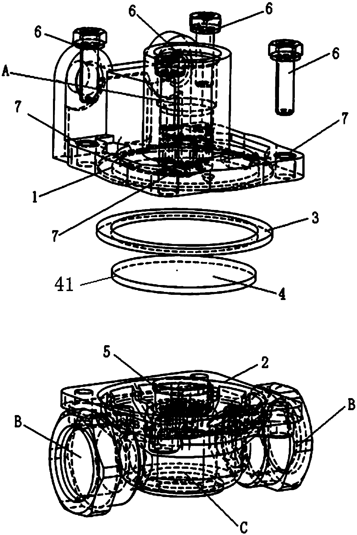
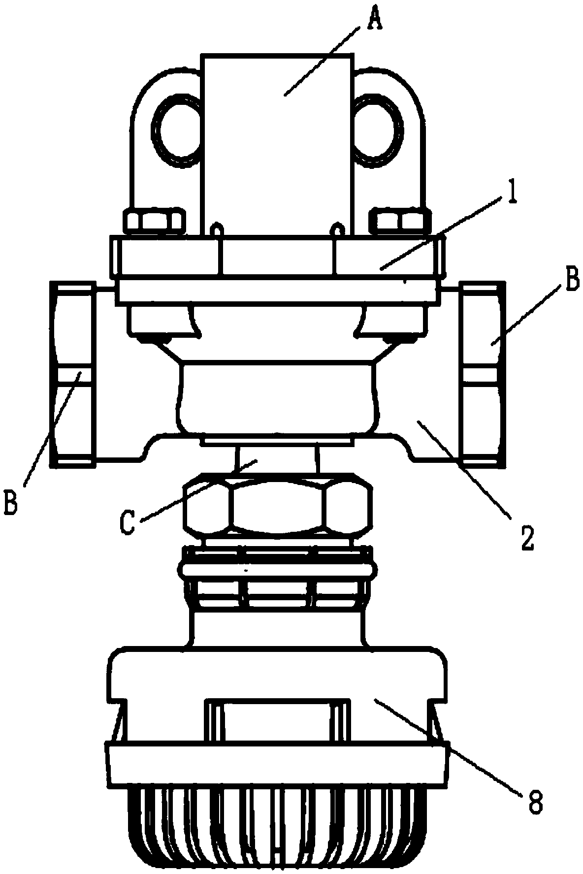
[0039] The application provides a quick release valve housing for braking, such as Figure 4 to Figure 7 As shown, it includes an upper case 200 and a lower case 500 , and the upper case 200 and the lower case 500 are fastened and connected by bolts 400 .

[0040] The upper casing 200 includes an upper casing body and an air inlet 201 arranged at the upper end of the upper casing, the air inlet 201 communicates with the inner cavity of the upper casing body; an air outlet is respectively arranged on both sides of the upper casing body 202. Each air outlet communicates with the inner cavity of the upper housing body; the upper housing body is provided with a mounting through hole for fixed connection with the lower housing through bolts.

[0041] The lower housing 500 includes a lower housing body and an exhaust valve 100, and the lower housing body and the exhaust valve are fixedly connected; in this application, the lower housing body and the exhaust valve are integrally form...

Embodiment 2

[0051] The present application provides a quick-release valve casing for braking, which includes an upper casing and a lower casing, and the upper casing and the lower casing are fastened and connected by bolts.

[0052] The upper casing includes an upper casing body and an air inlet arranged at the upper end of the upper casing, and the air inlet communicates with the inner cavity of the upper casing body; an air outlet is respectively arranged on both sides of the upper casing body, each The air outlets are all in communication with the inner cavity of the upper housing body; the upper housing body is provided with installation through holes for fixed connection with the lower housing through bolts.

[0053] The lower casing includes a lower casing body and an exhaust valve, and the lower casing body and the exhaust valve are fixedly connected; in this application, the lower casing body and the exhaust valve are integrally formed by casting.

[0054] The exhaust valve is pro...


PUM


Abstract

The invention relates to a quick release valve used for braking and a shell of the same. The shell comprises an upper shell body and a lower shell body. The upper shell body is tightly connected with the lower shell body through a bolt and comprises a main upper shell body and an air inlet formed in the upper end of the main upper shell body, and an air outlet is formed in each of two sides of the main upper shell body. The lower shell body comprises a main lower shell body and an exhaust valve, a boss structure recessing on the lower surface of the exhaust value and projecting on the upper surface of the exhaust valve is arranged on the exhaust valve, exhaust ports are formed in the top end of the boss structure, and central lines of the exhaust ports, a central line of the air inlet and a central line of the boss structure are coincided. According to the technical scheme, by improving a structure of an exhaust valve and improving the positions of the air outlet and the exhaust valve, impact on a membrane from a high-pressure airflow can be alleviated, the situation that the membrane impacted by the high-pressure airflow vibrates in high frequency is restrained, and squeaking during exhausting is alleviated.

Description

technical field [0001] The invention belongs to the technical field of brake systems, in particular to a brake quick-release valve housing and a quick-release valve. Background technique [0002] The quick release valve is used in truck pneumatic brake models, and it is generally arranged in the brake pipeline close to the brake chamber, which plays the role of quick exhaust when the brake is released, so as to quickly release the brake. [0003] The structure of the quick release valve in the prior art is as follows: Figure 1 to Figure 3 As shown, when assembling, stick the deflation valve 5 on the lower casing 2, place the sealing ring 3 in the pre-opened sealing groove of the upper casing 1, place the diaphragm 4 on the deflation valve 5 and use it four times. The bolt and the spring washer 6 pass through the bolt 7 and tightened. The above-mentioned assembly requires the centers of the two parts to be aligned. [0004] When the car brakes, the compressed air from the b...

Claims


Application Information

Patent Timeline
Patent Type & Authority Patents(China)
IPC IPC(8): B60T15/52
CPCB60T15/52
Inventor 王洪伟
Owner ANHUI JIANGHUAI AUTOMOBILE GRP CORP LTD
Why Eureka
Try Eureka