Pin Shearing Device

A shearing device and pin technology, applied in the field of machining and manufacturing, can solve the problems of complicated operation, inconvenient use and high cost, and achieve the effects of convenient use, satisfying use requirements and simple structure

Active Publication Date: 2016-06-08
SUZHOU & SCI & TECH DEV
View PDF6 Cites 0 Cited by
  • Summary
  • Abstract
  • Description
  • Claims
  • Application Information

AI Technical Summary

Problems solved by technology

At present, the processing methods of pins mainly adopt two processing methods: punching and casting, but the above two processing methods are cumbersome to operate, very inconvenient to use, and the cost of use is relatively high

Method used


Image

  • Pin Shearing Device
  • Pin Shearing Device
  • Pin Shearing Device

Examples


Embodiment Construction

[0015] The technical solutions of the present invention will be further described in detail below in conjunction with the accompanying drawings and preferred embodiments.

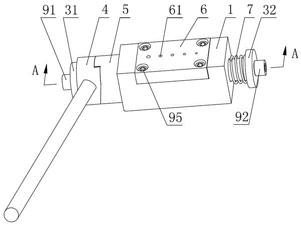
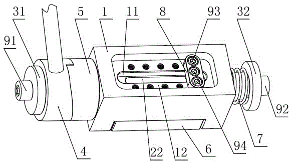
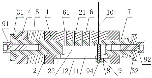
[0016] Such as figure 1 , figure 2 and image 3 As shown, the pin shearing device of the present invention includes a body 1 with a through hole through the front and back, and a through groove 11 vertically penetrating through the body 1 and the through hole is also opened on the body 1, and the moving rod 2 passes through the body 1 The body 1 extends out from the through hole on the top, and the first block 31 is locked on the front end of the moving rod 2 through the first locking bolt 91. A pressure rod 4 is movably sleeved on the moving rod 2, and the front end of the pressure rod 4 touches the front end of the moving rod 2. Leaning on the first stopper 31, a driving mechanism capable of driving the moving rod 2 to slide from back to front in the through hole is provided between the pressure rod 4 ...


PUM


Abstract

The invention discloses a pin shearing device, which comprises a body with a through hole and a through groove, the through groove and the through groove penetrate each other, a moving rod passes through the through hole, a first stopper is locked on the front end of the moving rod, A pressure rod is sleeved on the rod, and a driving mechanism for driving the moving rod to slide is arranged between the pressure rod and the body; The reset mechanism for the reset of the moving rod; the pin insertion block is embedded in the through groove at the upper end, a number of pin insertion holes with different diameters are arranged on the pin insertion block, and the first corresponding to each pin insertion hole is arranged on the moving rod. A through hole; a first groove is provided on the moving rod opposite to the lower end of the through groove, a second groove is provided at the lower end of the through groove, and a pin length is set to control the length of the sheared pin in the first and second grooves. Regulating mechanism. The invention has the advantages of simple structure, convenient use, and the ability to cut pins of various sizes and specifications.

Description

technical field [0001] The invention relates to the field of mechanical processing and manufacturing, in particular to a pin shearing device. Background technique [0002] The pin is one of the most commonly used connectors, and its main function is to determine the mutual position between the parts and prevent the relative position of the parts from being misaligned. At present, the processing methods of pins mainly adopt two processing methods of punching and casting, but the above two processing methods are cumbersome to operate, very inconvenient to use, and relatively high in cost. Contents of the invention [0003] The technical problem to be solved by the present invention is to provide a pin shearing device which is simple in structure, easy to use and capable of shearing pins of various sizes. [0004] In order to solve the above problems, the technical solution adopted in the present invention is: the pin shearing device includes a body with a through hole throu...

Claims


Application Information

Patent Timeline
Patent Type & Authority Patents(China)
IPC IPC(8): B23D79/00
Inventor 肖云峰周秋健陆强
Owner SUZHOU & SCI & TECH DEV
Why Eureka
Try Eureka