A led daylight lamp

A technology for lamps and daylight, which is applied in light sources, electric light sources, semiconductor devices of light-emitting elements, etc. It can solve the problems of single shape, high brightness, and the inability to adjust the light-emitting angle of the lamp tube, etc., and achieve the effect of free shape change

Inactive Publication Date: 2017-04-12
DAHOM FUJIAN ILLUMINATION TECH
View PDF7 Cites 0 Cited by
  • Summary
  • Abstract
  • Description
  • Claims
  • Application Information

AI Technical Summary

Problems solved by technology

The shape is single, and often only 1-2 fluorescent tubes can be installed in a lamp holder, and the lighting brightness is limited
And the light emitting angle of the lamp cannot be adjusted
The brightness of the area perpendicular to the fluorescent tube is particularly high, which is inconvenient in some cases and has certain limitations

Method used


Image

  • A led daylight lamp
  • A led daylight lamp
  • A led daylight lamp

Examples


Embodiment 1

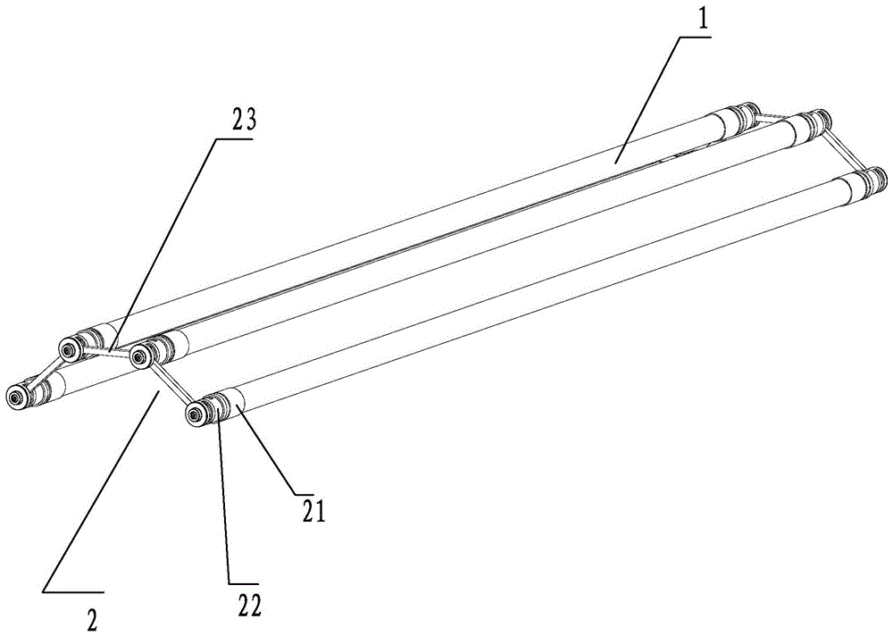
[0031] refer to figure 1 , an LED fluorescent lamp, comprising: at least 2 LED fluorescent tubes 1 and lamp holders 2, in this embodiment, the number of LED fluorescent tubes 1 is 4;

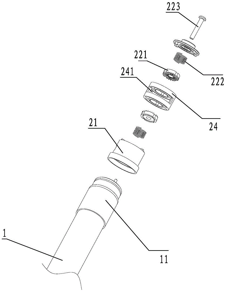
[0032] The lamp holder 2 includes: a base 21, the base 21 is provided with a pin hole, and the base 21 is electrically connected to the lamp holder 11 of the lamp tube 1;

[0033] A rotating mechanism 22, the rotating mechanism 22 is connected to the base 21;

[0034] A connecting mechanism 23 , the connecting mechanism 23 is connected between the rotating mechanisms 22 ; the connecting mechanism 23 can rotate around the rotating mechanism 22 .

[0035] And a connecting mechanism 23 connected between the rotating mechanisms 22 ; the connecting mechanism 23 can rotate around the rotating mechanism 22 .

[0036] further reference figure 2 , the rotating mechanism 22 includes: a damping gear 221 and a return spring 222 connected thereto, and the return spring 222 is connected to the damping gea...

Embodiment 2

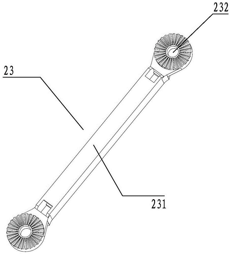
[0042] refer to Figure 4 , Figure 5 . The difference between this embodiment and the first embodiment is that the rotating mechanism 22 is an elastic damping gear, and the elastic damping gear includes an elastic blocking piece 221 . The connecting mechanism 23 is a connecting rod 231 , two ends of the connecting rod 231 are provided with prongs 232 distributed in a circle, and the elastic blocking piece 221 is clamped between the prongs 232 .

[0043] When the connecting rod 231 rotates, the tooth tip 232 presses the elastic blocking piece 221 to deform the elastic blocking piece 221 to generate damping. When the connecting rod 231 turns over a tooth tip 232, the elastic blocking piece The slice 221 is reset. Through the above design, the purpose of individually adjusting the position of each LED fluorescent tube 1 is achieved.

[0044] The rest of this embodiment is the same as the first embodiment, and will not be repeated here.

Embodiment 3

[0046] refer to Figure 6 , The difference between this embodiment and Embodiment 1 is that: there are two rotating mechanisms 22, and they are respectively arranged on both sides of the base 21. The lamp holder 2 is provided with a hanging hole 25, so that the LED daylight lamp can be hoisted. Such as Figure 7 shown.

[0047] The rest of this embodiment is the same as Embodiment 2, and will not be repeated here.


PUM


Abstract

The invention provides an LED fluorescent lamp which comprises at least two LED fluorescent lamp tubes and lamp brackets. The lamp brackets comprise bases, rotating mechanisms and connecting mechanisms; pin holes are formed in the bases, and the bases are electrically connected with lamp holders of the lamp tubes; the rotating mechanisms are connected with the bases; each connecting mechanism is connected between the corresponding rotating mechanisms; the connecting mechanisms can rotate around the rotating mechanisms. The LED fluorescent lamp has the advantages that the multiple LED fluorescent lamp tubes can be connected with one another by the rotating mechanisms and the connecting mechanisms, the quantity of the connecting mechanisms can be increased and decreased, accordingly, the quantity of the LED fluorescent lamp tubes can be adjusted, and the LED fluorescent lamp is simple and practical; the connecting mechanisms of the LED fluorescent lamp can rotate around the rotating mechanisms, accordingly, the fluorescent lamp tubes can be repositioned relatively to form different shapes, illuminating angles can be adjusted, and light rays can be scattered or gathered according to actual requirements.

Description

technical field [0001] The invention relates to an illuminating device, in particular to an LED daylight lamp. Background technique [0002] As one of the most common lighting fixtures, fluorescent lamps are widely used in all walks of life. Traditional daylight lamps consist of a lamp holder and a lamp tube, and the lamp holder needs to be pre-installed on the ceiling. The shape is single, and often only 1-2 fluorescent tubes can be installed in one lamp holder, so the lighting brightness is limited. And the light emitting angle of the lamp tube cannot be adjusted. As a result, the brightness of the area perpendicular to the fluorescent tube is particularly high, which is inconvenient in some cases and has certain limitations. Contents of the invention [0003] The main technical problem to be solved by the present invention is to provide an LED fluorescent lamp, which can connect at least two LED fluorescent tubes at the same time, and form various shapes by changing ...

Claims


Application Information

Patent Timeline
Patent Type & Authority Patents(China)
IPC IPC(8): F21S8/06F21V21/14F21Y115/10
Inventor 吴琼林志怀陈林
Owner DAHOM FUJIAN ILLUMINATION TECH
Why Eureka
Try Eureka