Bearing frame

A technology of bearing frame and bottom plate, which is applied in the field of bearing frame of bearing storage device, to achieve the effect of reducing complicated procedures, preventing vertical movement and improving fixity

Inactive Publication Date: 2014-12-03
INVENTEC PUDONG TECH CORPOARTION +1
View PDF7 Cites 0 Cited by
  • Summary
  • Abstract
  • Description
  • Claims
  • Application Information

AI Technical Summary

Problems solved by technology

Bottom plate for carrying storage devices

Method used


Image

  • Bearing frame
  • Bearing frame
  • Bearing frame

Examples


Embodiment Construction

[0028] A number of embodiments of the present invention will be disclosed in the following figures. For the sake of clarity, many practical details will be described together in the following description. It should be understood, however, that these practical details should not be used to limit the invention. That is, in some embodiments of the present invention, these practical details are unnecessary. In addition, for the sake of simplifying the drawings, some conventional structures and components will be shown in a simple and schematic manner in the drawings.

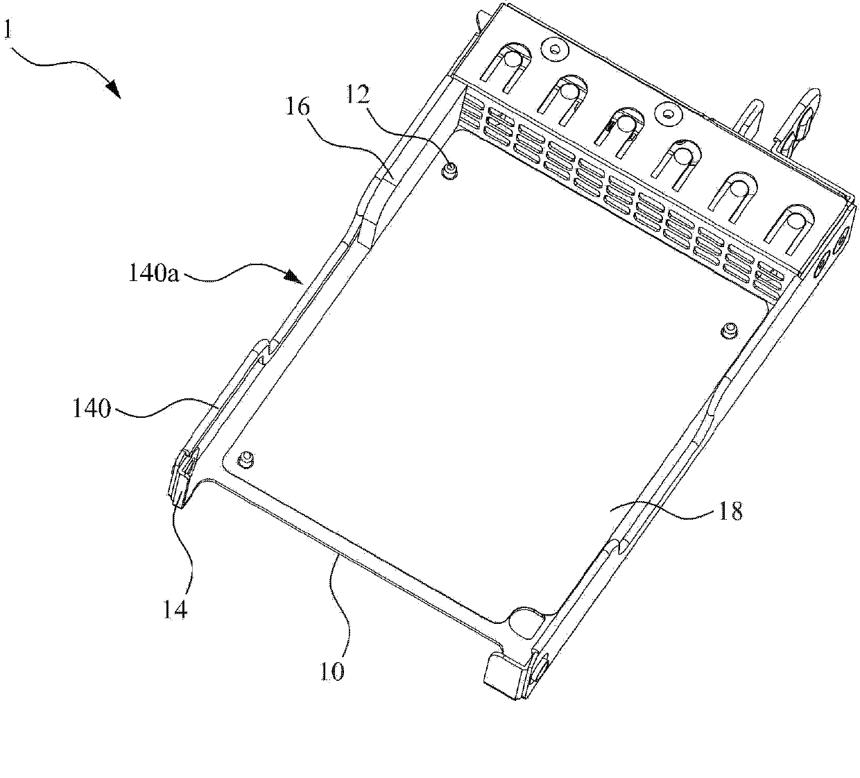
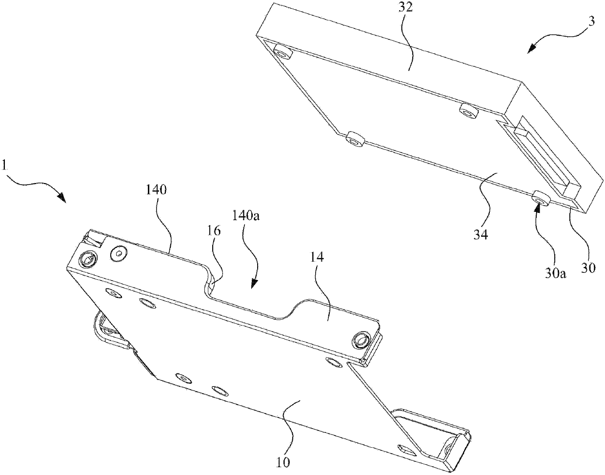
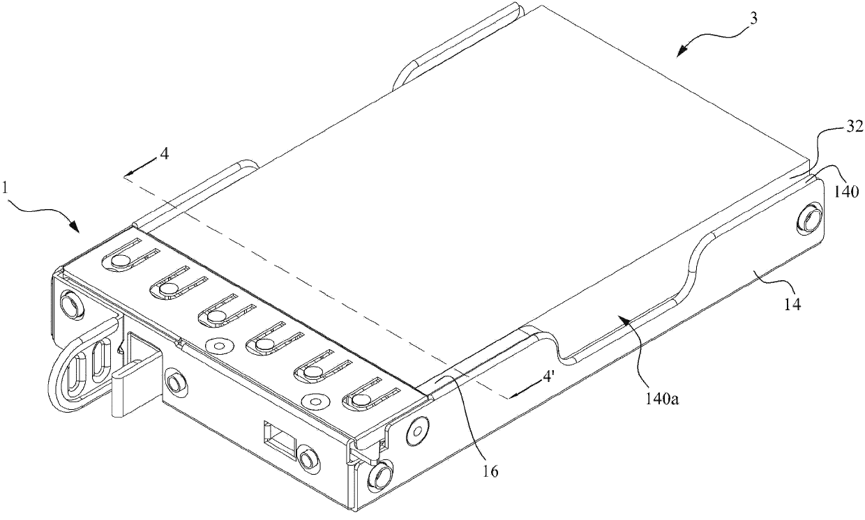
[0029] Please refer to figure 1 , figure 2 as well as image 3 . figure 1 It is a three-dimensional view illustrating a carrying frame 1 according to an embodiment of the present invention. figure 2 for illustration figure 1 The three-dimensional exploded view of the carrying frame 1 and the storage device 3 in . image 3 for illustration figure 2 The three-dimensional combined view of the carrying frame ...


PUM


Abstract

The invention discloses a bearing frame, which is used for bearing a storage device. The bottom of the storage device is provided with a plurality of threaded holes. The bearing frame comprises a bottom plate, a plurality of locating pins, a side wall and a shock absorbing piece. The bottom plate is used for bearing the storage device. Each locating pin is arranged on the bottom plate and is inserted into and clamped with the corresponding threaded hole, so as to prevent the storage device from moving or rotating horizontally relative to the bottom plate. The side wall is connected with the bottom plate. The shock absorbing piece is arranged on the side wall and is arranged between the side wall and at least one of the locating pins. The shock absorbing piece is clamped and squeezed between the side wall and the storage device, so as to prevent the storage device from leaving the bottom plate along a direction perpendicular to the bottom plate.

Description

technical field [0001] The present invention relates to a carrying frame, in particular to a carrying frame for carrying a storage device. Background technique [0002] Currently, there are many ways to fix storage devices (for example, hard disks or optical disk drives) in the computer industry. Usually, the most widely used method is to directly lock the storage device on the computer case by using screws. [0003] Along with the continuous improvement of computer, there have been some fixed mounts that are convenient for assembly and disassembly. One of the traditional fixing frames is used to carry the storage device, and the storage device is locked by screws. After the fixing frame with the storage device is inserted into the computer casing along the guides in the computer casing, the fixing frame must be locked to the computer casing with screws, and then the storage device is fixed in the computer casing. Location. When performing subsequent maintenance or repla...

Claims


Application Information

Patent Timeline
IPC IPC(8): G06F1/18
Inventor 陈亦宣
Owner INVENTEC PUDONG TECH CORPOARTION
Why Eureka
Try Eureka