Water softener manifold retainer assembly

Inactive Publication Date: 2005-03-10
BANK OF AMERICA N A
View PDF6 Cites 1 Cited by
  • Summary
  • Abstract
  • Description
  • Claims
  • Application Information

AI Technical Summary

Benefits of technology

[0008] The above-listed needs are met or exceeded by the present manifold retainer assembly. To provide a retainer assembly which prevents vertical movement of the manifold, a seat is attached to the manifold for receiving a retainer base. The retainer base is disposed on top of the seat. At least one, and preferably a plurality of retaining protrusions are positioned in an extended position and secured to the retainer base. In this extended position, the retaining protrusions extend beyond the peripheral edges of the retainer base. Additionally, the retaining protrusions are in close proximity to the underside of the tank head, preventing vertical movement of the manifold.

Problems solved by technology

Due to the density of the resin in the tank, once withdrawn it is extremely difficult to replace the manifold back into position within the resin without first emptying the tank, which wastes time and resources.
This inlet water flowing directly adjacent to the manifold, in a process also known as channeling, causes premature exhaustion of the media.
When the water treatment tank experiences increasingly low water flow in the service position, the channeling described above is more noticeable or problematic.
Thus, the water treatment system becomes inefficient because of the premature bypass of unconditioned water through the treatment media.

Method used


Image

  • Water softener manifold retainer assembly
  • Water softener manifold retainer assembly
  • Water softener manifold retainer assembly

Examples


Embodiment Construction

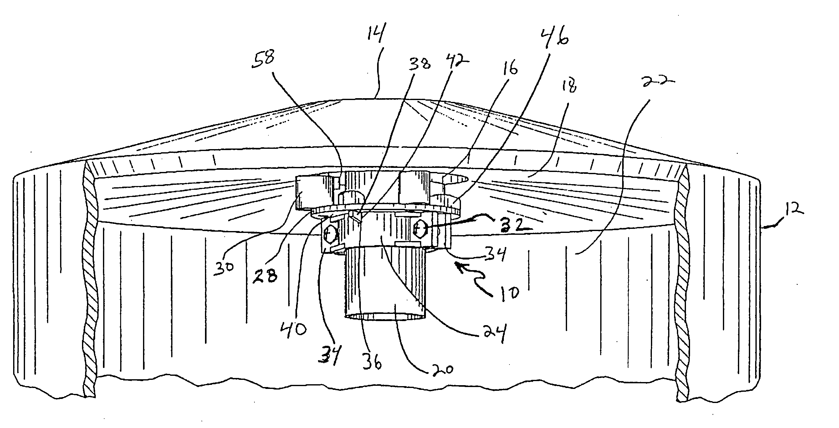
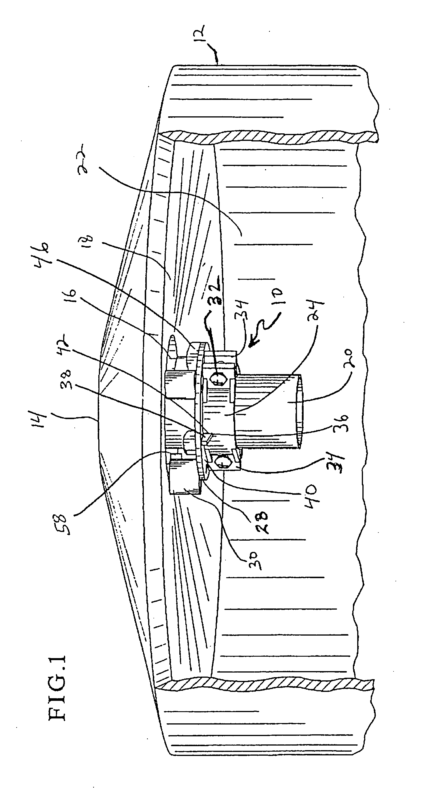
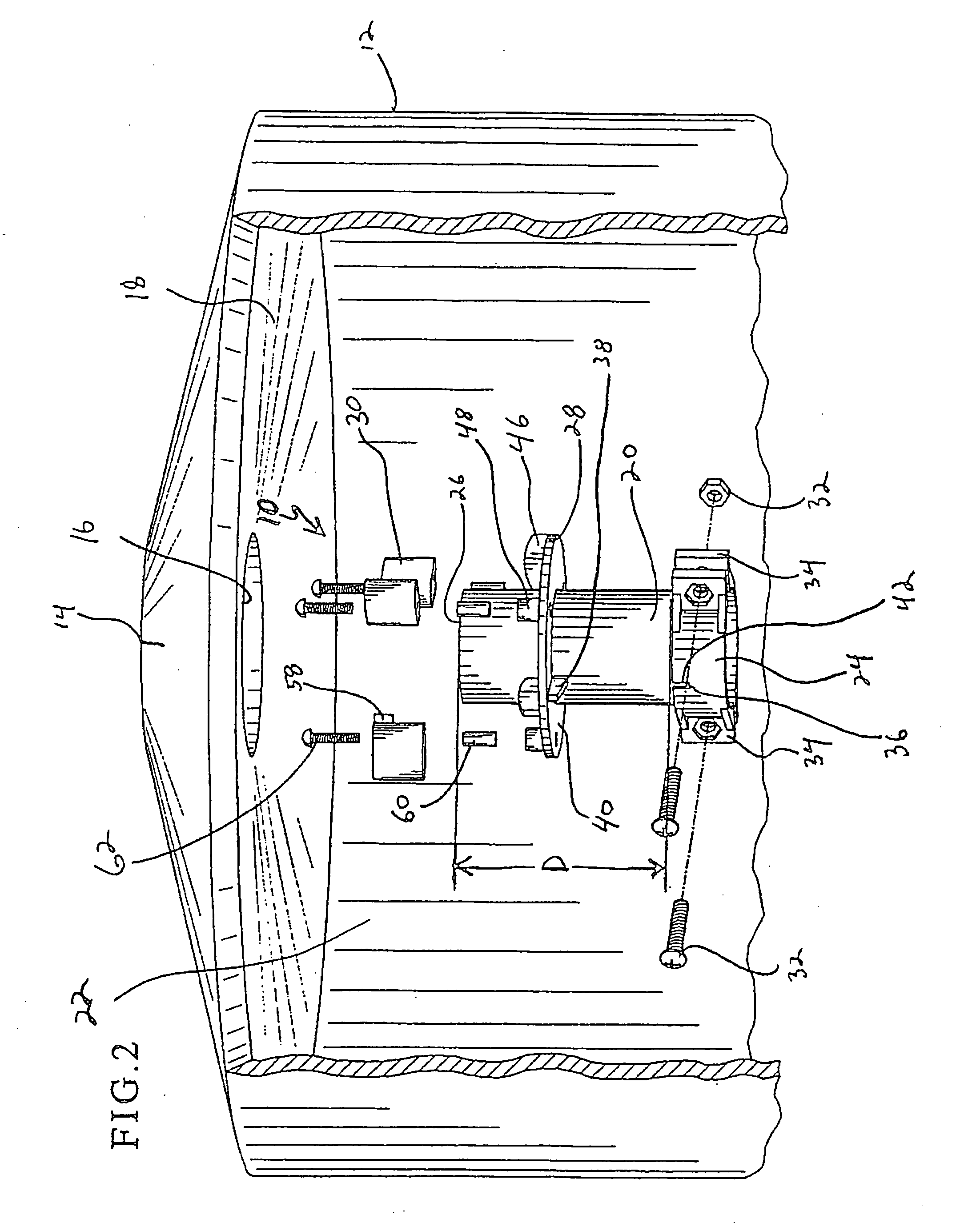
[0015] Referring now to FIGS. 1 and 2, a retainer assembly for a water softener is generally designated 10. As is well known in the art, water softener treatment tanks include an enclosed chamber in which a supply of resin media is contained. As hard water passes through the media, Ca+ and Mg+ ions are bonded to media and replaced by Na+ ions. Examples of such water softener treatment tanks are described in U.S. Pat. No. 6,032,821, which is hereby incorporated by reference. As described above, in many conventional treatment tanks, when a control valve is removed from a tank head, a manifold becomes stuck to the valve. The valve rotates due to threaded valve design and is lifted during and after rotation. This movement often causes vertical and / or rotational forces to be applied to the manifold and may cause movement of the manifold. As the manifold moves or rotates, the media surrounding the manifold falls underneath it, making an almost impossible task of placing the manifold back ...


PUM


Abstract

A retainer assembly for maintaining the position of a manifold in a tank includes a seat configured for attachment adjacent an end of the manifold. A retainer base is configured for engaging the seat, which retains the base relative to the manifold. At least one retaining protrusion is securable to the base for movement between a first, retracted position and a second, extended position.

Description

FIELD OF THE INVENTION [0001] The present invention relates generally to water treatment tanks of the type used in water softening and / or filtering systems. More particularly, the present invention relates to retainer assemblies for preventing the movement of a manifold out of such a treatment tank when a valve head is removed from the tank. BACKGROUND OF THE INVENTION [0002] Water treatment tanks are known and used to condition or soften water. Conventional tanks have a tank head that provides an inlet and an outlet for the water flow through penetrating fittings or collars. In these conventional tanks, as water enters the tank through an inlet, it is directed through a media or bed of resin beads. At the bottom of the bed, treated water flows from the bottom of the tank into a tubular manifold to the top of the tank. In other embodiments, untreated water is introduced at the bottom of the tank and flows upwardly. In either embodiment, the treated water then exits the tank through ...

Claims


Application Information

Patent Timeline
IPC IPC(8): B01J47/02C02F1/42
CPCC02F1/42B01J47/022Y10T137/86372
Inventor PELTASON, KEITHWEBB, LONNIE
Owner BANK OF AMERICA N A
Why Eureka
Try Eureka