Air suction device on embroiderer rack

An embroidery machine and frame technology, which is applied to the mechanism of embroidery machines, embroidery machines, sewing equipment, etc., can solve the problems of energy waste, increased use cost, and small suction range, so as to reduce use cost, reduce energy consumption, Energy Saving Effect

Active Publication Date: 2014-12-24
汕头市坤兴刺绣有限公司
View PDF10 Cites 11 Cited by
  • Summary
  • Abstract
  • Description
  • Claims
  • Application Information

AI Technical Summary

Problems solved by technology

[0005] The embroidery machine needs to be cleaned automatically at regular intervals, and the entire operation process can be completed with the help of the air suction device installed on it. However, the structure of the air suction device on the embroidery machine frame is currently insufficient. Since there is only one suction port on the suction device, it cannot To meet the actual needs, such as some places need a large suction, some places only need a small suction, but the existing suction port does not have a variety of suction ports, only one suction port, resulting in only one suction port in the actual operation process Using a uniform power for suction work cannot meet the existing actual suction requirements, which increases the cost of use and causes unnecessary waste of energy
[0006] In addition, the existing air suction devices are generally fixed and inconvenient, unable to adjust the height, and the working suction range is small, which cannot meet the suction work of other parts, so the overall needs to be improved

Method used


Image

  • Air suction device on embroiderer rack
  • Air suction device on embroiderer rack
  • Air suction device on embroiderer rack

Examples


Embodiment Construction

[0029] The present invention will be further described below in conjunction with the accompanying drawings and embodiments.

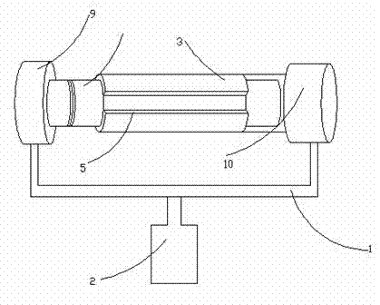
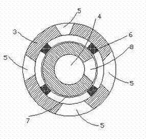
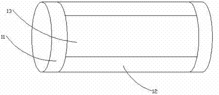
[0030] Reference attached figure 1 , attached figure 2 And attached image 3 , this embodiment discloses an air suction device on an embroidery machine frame, which is characterized in that it includes a suction pipe and a suction pump connected to the suction pipe, and the suction pipe is provided with a cylinder 2 through a bracket 1 The air suction pipe includes an outer pipe 3 and an inner pipe 4, a plurality of air suction ports 5 of different sizes are formed on the wall of the outer pipe 3, and fixed air suction ports 5 are arranged on the inner wall and both sides of the air suction port 5; A strip-shaped rubber table 6, the strip-shaped rubber table 6 is jointly connected with a fixed plate 7, and the inner tube 4 is connected by a bearing on the inner wall of the fixed plate 7, and one end of the inner tube 4 is an open end, and The suctio...


PUM


Abstract

The invention discloses an air suction device on an embroiderer rack. The air suction device is characterized by comprising an air suction pipe and an air suction pump connected with the air suction pipe, the air suction pipe is provided with a steam cylinder through a bracket and comprises an outer pipe and an inner pipe, a plurality of different air suction openings are formed in the pipe wall of the outer pipe, fixed strip-shaped rubber platforms are arranged on the two sides of the air suction openings on the inner wall and are connected with a fixing plate together, the inner pipe is connected on the inner wall of the fixing plate through a bearing, one end of the inner pipe is an open end and is connected with the air suction pump, an air outlet is arranged on the pipe wall of the inner pipe, the other end of the inner pipe is a closed end, a first drive motor is arranged at the closed end, a second drive motor is arranged at one end of the outer pipe, and the first drive motor and the second drive motor are arranged on the bracket. The air suction device of the embroiderer rack forms an air suction surface, so that the operation range is regulated, the air suction amount is also regulated, the practical operation requirements are met, the cost is saved, and the energy consumption is reduced.

Description

technical field [0001] [0002] The invention relates to an air suction device on an embroidery machine frame. [0003] Background technique [0004] [0005] The embroidery machine needs to be cleaned automatically at regular intervals, and the entire operation process can be completed with the help of the air suction device installed on it. However, the structure of the air suction device on the embroidery machine frame is currently insufficient. Since there is only one suction port on the suction device, it cannot To meet the actual needs, such as some places need a large suction, some places only need a small suction, but the existing suction port does not have a variety of suction ports, only one suction port, resulting in only one suction port in the actual operation process Using a uniform power to carry out the suction operation cannot meet the existing actual suction requirements, which increases the use cost and causes unnecessary waste of energy. [0006] In a...

Claims


Application Information

Patent Timeline
Patent Type & Authority Applications(China)
IPC IPC(8): D05C13/00
Inventor 徐挺
Owner 汕头市坤兴刺绣有限公司
Why Eureka
Try Eureka