
Camera monitoring alarm method and device

A technology for monitoring alarm devices and cameras, applied to alarms, instruments, etc., can solve problems such as low recognition rate, large amount of movement, and large changes in light and shadow

Inactive Publication Date: 2014-12-24
ZHEJIANG DAHUA TECH CO LTD
View PDF5 Cites 2 Cited by
  • Summary
  • Abstract
  • Description
  • Claims
  • Application Information

AI Technical Summary

Problems solved by technology

[0004] This image intelligence algorithm has the problems of low recognition rate and high false alarm rate in the following scenarios:
[0005] 1. The brightness of the monitored scene is low, such as night and dark places;
[0006] 2. When the video content changes greatly (the monitored scene has many moving objects and a large amount of movement), etc.;
[0007] 3. Large changes in light and shadow, weather effects
[0008] In these scenarios, the accuracy rate of recognition through intelligent recognition is low, and there are a large number of false alarms, so it is impossible to accurately determine the abnormality of the camera
Moreover, there is often a delay in the use of image intelligence algorithms. In the monitoring system, it is impossible to feed back abnormal information in time for a large number of cameras.
[0009] In summary, under the existing technology, managers cannot accurately and timely grasp the working status of the camera

Method used


Image

  • Camera monitoring alarm method and device
  • Camera monitoring alarm method and device
  • Camera monitoring alarm method and device

Examples


Embodiment 1

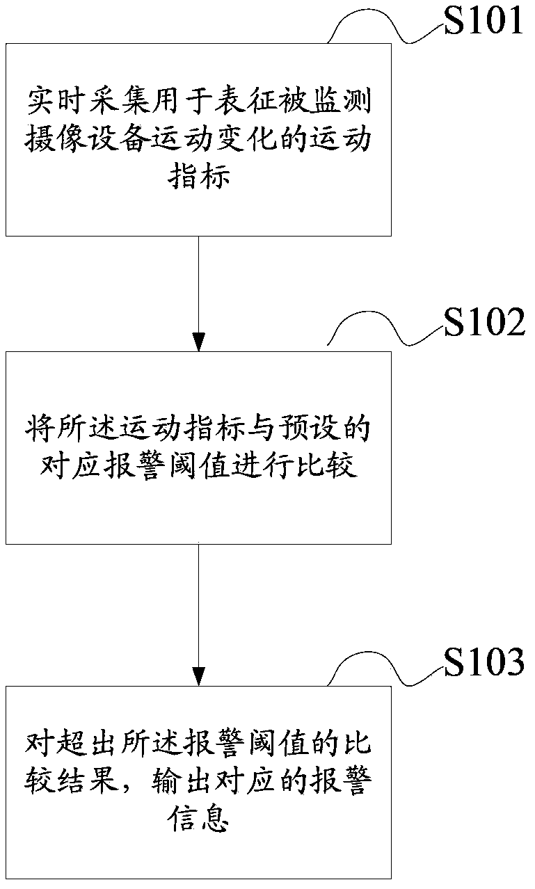
[0024] First, the embodiment of the present invention provides a camera monitoring and alarm method, such as figure 1 As shown, the method includes:

[0025] S101, collecting in real time motion indicators used to characterize motion changes of the monitored camera equipment;

[0026] S102, comparing the motion index with a preset corresponding alarm threshold;

[0027] S103. For the comparison result exceeding the alarm threshold, output corresponding alarm information.

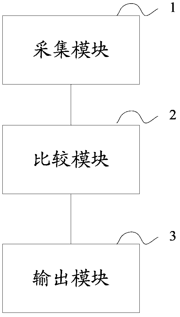
[0028] In the embodiment of the present invention, a monitoring mechanism is adopted, and an alarm threshold is set as required, compared with the motion index of the real-time collected camera equipment, and an alarm message is output immediately when the threshold is exceeded. It can be understood that the alarm information can be output to the upper-level equipment in the form of information, or directly in the form of sound, light, etc., in order to remind the manager in time that the abnormal displace...


PUM


Abstract

The invention discloses a camera monitoring alarm method and device. The method and device are used for monitoring the positions and movement conditions of a camera in real time and can send out alarm information in time when the camera moves. The method includes the steps that movement indexes which represent movement changes of the monitored camera are collected in real time; the movement indexes are compared with a preset corresponding alarm threshold value; the corresponding alarm information is output according to the comparison result that the movement indexes exceed the alarm threshold value.

Description

technical field [0001] The invention relates to the technical field of monitoring and alarming, in particular to a camera monitoring and alarming method and device. Background technique [0002] In today's daily life, there are basically situations where cameras are used to monitor scenes, such as traffic probes, community probes, and so on. In the process of using the camera to monitor, the camera has the function of shooting the monitoring scene. Generally, it will be fixed or reciprocating to patrol the set area. If it is artificially damaged, such as knocking, etc., it will cause the camera body to move abnormally. In addition to human factors, the long-term outdoor environment may also cause damage to the bracket, which indirectly leads to abnormal shifting of the camera. These situations will cause abnormal changes in the monitoring area of ​​the shifted camera, and the preset monitoring cannot be achieved. Purpose. [0003] The existing monitoring of camera position...

Claims


Application Information

Patent Timeline
Patent Type & Authority Applications(China)
IPC IPC(8): G08B21/00
Inventor 殷俊张兴明傅利泉朱江明吴军吴坚
Owner ZHEJIANG DAHUA TECH CO LTD
Learn More