Automatic lacing equipment on basis of shoe upper and control method thereof

A technology for automatic lacing and shoelaces, which is applied in the direction of footwear, shoe bindings, clothing, etc., can solve problems such as troublesome, inefficient, and failure, and achieve the effects of convenient use, liberating labor force, and improving work efficiency

Active Publication Date: 2014-12-31
SUZHOU DALIKE AUTOMATION TECH
View PDF7 Cites 24 Cited by
  • Summary
  • Abstract
  • Description
  • Claims
  • Application Information

AI Technical Summary

Problems solved by technology

[0002] Nowadays, in many shoe factories and other places, shoelaces are worn by hand, which is troublesome, laborious, inefficient and expensive
[0003] Moreover, there is no ready-made device for wearing shoelaces on the market now. Although some people have tried the research and development of shoelace-wearing equipment before, they all ended in failure in the end. Shoelace device and control method thereof

Method used


Image

  • Automatic lacing equipment on basis of shoe upper and control method thereof
  • Automatic lacing equipment on basis of shoe upper and control method thereof

Examples


specific Embodiment 1

[0057] A control method for an automatic shoelace-wearing device based on a shoe upper, the steps of which include:

[0058] A. Set or calculate the length of the shoelace, the width of the upper, the distance between the shoelace holes, the moving distance of the first belt threader, the moving distance of the second belt threader, the Information such as moving distance, threading order of shoelace holes, and shoelace threading method;

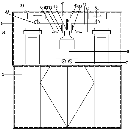
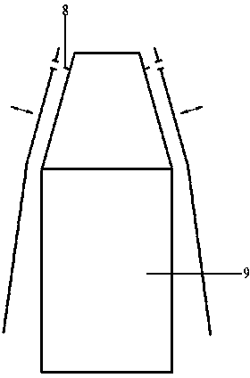
[0059] B. Adjust the position of the pedestal from front to back, fix the upper on the fixture, insert the pins into the two shoelace holes at the top of the upper, and at the same time put the head of the upper on the positioning sleeve for positioning;

[0060] C. Adjust the positions of the first lace threader, the second lace threader, the third lace threader and the shoelace delivery device so that the second shoelace clip is located in the upper, and the first shoelace clip and the third shoelace clip are in the The left and right sid...

specific Embodiment 2

[0074] A control method for an automatic shoelace-wearing device based on a shoe upper, the steps of which include:

[0075] A. Set or calculate the length of the shoelace, the width of the upper, the distance between the holes of the shoelace, the moving distance of the first belt threader, the moving distance of the second belt threader, the Information such as moving distance, threading order of shoelace holes, and shoelace threading method;

[0076] B. Adjust the position of the pedestal before and after, fix the upper on the fixture, put the pins into the two shoelace holes at the top of the upper, and at the same time put the head of the upper on the positioning sleeve for positioning;

[0077] C. Adjust the positions of the first lace threader, the second lace threader, the third lace threader and the shoelace delivery device so that the second shoelace clip is located in the upper, and the first shoelace clip and the third shoelace clip are in the The left and right s...


PUM


Abstract

The invention discloses automatic lacing equipment on the basis of a shoe upper and a control method thereof. The automatic lacing equipment comprises a main frame body, an equipment bracket, a first lacer, a second lacer, two shoelace conveying devices, a pedestal and a shoe upper fixture. By the mode, the automatic lacing equipment on the basis of the upper and the control method thereof, which are disclosed by the invention, can implement the mechanical lacing work, liberate labor, improve working efficiency and are convenient to use.

Description

technical field [0001] The invention relates to the field of shoelace-wearing equipment, in particular to an automatic shoelace-wearing equipment based on a shoe upper and a control method thereof. Background technique [0002] Now in many shoe factories and other places, shoelaces are worn by hand, which is troublesome, laborious, inefficient and costly. [0003] Moreover, there is no ready-made device for wearing shoelaces on the market now. Although some people have tried to develop shoelaces before, they all ended in failure. A shoelace device and a control method thereof. Contents of the invention [0004] The technical problem mainly solved by the present invention is to provide an automatic shoelace-wearing device based on shoe uppers and its control method, which has the advantages of high reliability, precise positioning, simple structure, high work efficiency, and convenient use. It has a broad market prospect in terms of application and popularization. [000...

Claims


Application Information

Patent Timeline
Patent Type & Authority Applications(China)
IPC IPC(8): A43C7/00
Inventor 丁慎平肖舫代昌浩
Owner SUZHOU DALIKE AUTOMATION TECH
Why Eureka
Try Eureka